Hydraulic speed regulating valve

A technology of speed control valve and hydraulic pressure, which is applied in the field of hydraulic speed control valves to achieve the effects of reducing energy consumption, avoiding oil leakage, and maintaining stable speed control range

Active Publication Date: 2015-04-22
ZHEJIANG HAIHONG HYDRAULIC TECH
View PDF6 Cites 4 Cited by
  • Summary
  • Abstract
  • Description
  • Claims
  • Application Information

AI Technical Summary

Problems solved by technology

[0005] The purpose of the present invention is to solve the above problems in the existing technology, and propose a hydraulic speed regulating valve. The technical problem solved by the present invention is how to reduce the energy consumption of the hydraulic speed regulating valve

Method used


Image

  • Hydraulic speed regulating valve
  • Hydraulic speed regulating valve
  • Hydraulic speed regulating valve

Examples


Embodiment 1

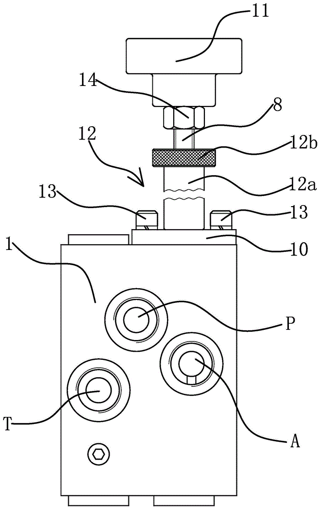
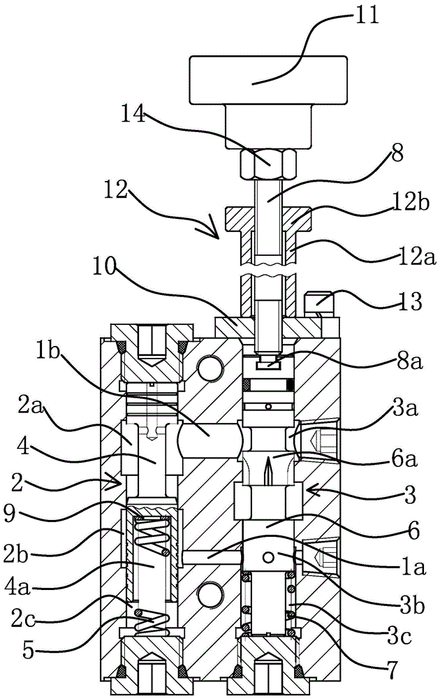
[0033] The hydraulic speed regulating valve includes a valve body 1, a fixed differential overflow valve chamber 2, a throttle valve chamber 3, a fixed differential overflow valve core 4, a throttle valve core 6 and a speed regulating valve stem 8.

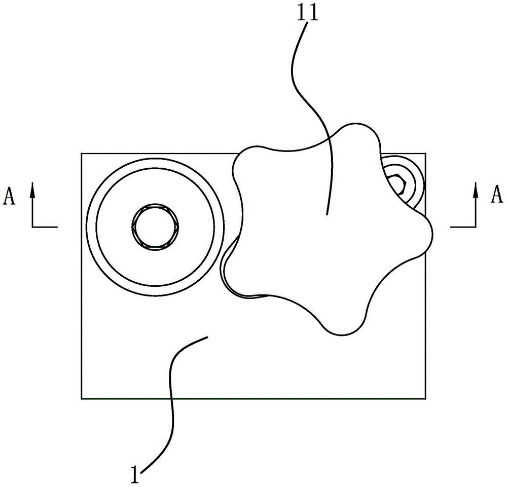
[0034] As a specific implementation, such as figure 2 with image 3 As shown, the differential relief valve cavity 2 and the throttle valve cavity 3 are set in the valve body 1 respectively. In this embodiment, the differential relief valve cavity 2 and the throttle valve cavity 3 are arranged parallel to each other. Body 1, after the processing is completed, it is blocked by plugging. The structure and processing method of the valve body 1 maximize the use of the space in the valve body 1, so that the volume of the hydraulic speed regulating valve can be made smaller. Such as figure 1 As shown, the valve body 1 is also provided with an oil inlet P, an oil return port T and a working port A.

[0035] Such as image 3 As sho...

Embodiment 2

[0054] The technical solution in this embodiment is basically the same as that in the first embodiment, the difference is that in this embodiment, the differential relief valve cavity 2 and the throttle valve cavity 3 are located in two independent valve bodies 1 . It should be noted that as an evolution of the technical solution, as long as the connection method is the same as the technical solution to be protected by the claims, even if the differential relief valve cavity 2 and the throttle valve cavity 3 are arranged in two independent valve bodies 1 ( For example, the differential relief valve and throttle valve sold in the market are connected in series), and it should also be considered that this solution falls within the protection scope of the claims of the present application.

Embodiment 3

[0056] The technical solution in this embodiment is basically the same as that in Embodiment 1, the difference is that in this embodiment, the hydraulic speed regulating valve is applied to agricultural machinery. Agricultural machinery refers to various machinery used in crop planting and animal husbandry production, as well as in the primary processing and handling of agricultural and animal products. The agricultural machinery used in the crop planting industry can be divided into farming machinery, planting machinery and harvesting machinery according to their functions. The most typical of the farming machinery is the rotary tiller, and the most typical of the harvesting machinery is the combine harvester.

[0057] The mechanical structure of agricultural machinery in the planting industry includes the walking mechanism that drives the agricultural machinery to move on the field and the actuator used to complete the plowing, planting, and harvesting actions. For example, ...


PUM


Abstract

The invention provides a hydraulic speed regulating valve, and belongs to the technical field of hydraulic pressure. The hydraulic speed regulating valve solves the problems that an existing hydraulic speed regulating valve is large in energy consumption and serious in heat emission. The hydraulic speed regulating valve comprises a valve body in which a constant-difference overflow valve cavity and a throttling valve cavity are formed, the constant-difference overflow valve cavity is provided with an oil inlet valve cavity and an oil returning valve cavity, a constant-difference overflow valve element is arranged in the constant-difference overflow valve cavity, an overflow spring is further arranged between the constant-difference overflow valve element and the valve body, and the end, provided with the overflow spring, of the constant-difference overflow valve cavity is a feedback regulation valve cavity; a throttling segment is arranged in the throttling valve cavity, the portion, close to the throttling segment, of the throttling valve cavity is provided with a work valve cavity communicated with a work port, a throttling valve element is arranged in the throttling valve cavity, a throttling spring is arranged at one end of the throttling valve element, and the other end of the throttling valve element is provided with a speed regulating valve rod stretching out of the valve body; the oil inlet valve cavity is communicated with the throttling segment, and the work valve cavity is communicated with the feedback regulation valve cavity. Redundant hydraulic oil of the hydraulic speed regulating valve is directly conveyed back to an oil tank, and energy consumption and heat emission of the hydraulic speed regulating valve are reduced.

Description

technical field [0001] The invention belongs to the technical field of hydraulic pressure and relates to a hydraulic speed regulating valve. Background technique [0002] The function of the hydraulic speed regulating valve is to keep the flow of hydraulic oil at the set value and not change with the change of the external load. At present, the speed regulating valves on the market are mostly composed of differential pressure reducing valves and throttle valves connected in series. The pressure difference before and after the flow valve is a constant value, thus eliminating the influence of load changes on the flow. [0003] For example, the Chinese patent [application number 201320323049.1; authorized announcement number CN 203488759U] discloses a quick speed regulating valve, which includes a pressure reducing valve, a throttle valve connected in series with the pressure reducing valve, located on one side of the pressure reducing valve and connected to the pressure reduc...

Claims


Application Information

Patent Timeline
Patent Type & Authority Applications(China)
IPC IPC(8): F15B13/02
CPCF15B13/02
Inventor 呼延宏杨济铭何贤剑陈净生高振家綦剑孙寅虎陈善民
Owner ZHEJIANG HAIHONG HYDRAULIC TECH
Why Eureka
Try Eureka