
Cryogenic liquid storage tank test full structure

A low-temperature liquid storage tank technology, applied in the field of low-temperature liquid storage tank test full structure, can solve the problems of non-compliance with safety requirements, time-consuming and labor-intensive problems

Inactive Publication Date: 2016-06-15
CHANGZHOU BURAN CRYOGENIC EQUIP
View PDF7 Cites 0 Cited by
  • Summary
  • Abstract
  • Description
  • Claims
  • Application Information

AI Technical Summary

Problems solved by technology

This method of direct discharge into the air does not meet the safety requirements
[0003] At the outlet of the concentrated discharge, the conventional method is to connect the two ends of the tee to the upward elbow, the outlet of the elbow is sealed with a 50-mesh steel mesh, and the lower end of the elbow is drilled with a Φ10 small hole for rainwater drainage. Time-consuming and labor-intensive practice of discharge export structure

Method used


Image

  • Cryogenic liquid storage tank test full structure

Examples


Embodiment Construction

[0019] In order to make the content of the present invention more clearly understood, the present invention will be further described in detail below based on specific embodiments and in conjunction with the accompanying drawings.

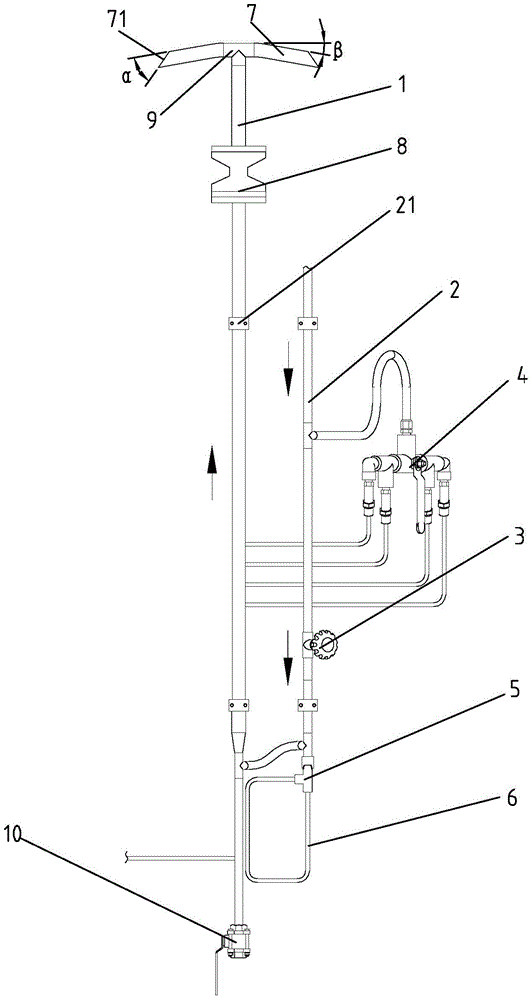
[0020] Such as figure 1 Shown, a kind of cryogenic liquid storage tank test full structure is characterized in that, it comprises:

[0021] Concentrated discharge pipe 1;

[0022] The test full pipe 2 is equipped with a test full valve 3, and the part of the test full pipe 2 above the test full valve 3 is the safety discharge part, and the part of the test full pipe 2 below the test full valve 3 is the test full pipe 2. The full test part and the safety relief part are connected to the centralized discharge pipe 1 through the safety valve group 4;

[0023] The movable connector 5 is connected to the lower end of the full test part;

[0024] The test full test circuit 6, the inlet of the full test test circuit 6 is connected with the movable conn...


PUM


Abstract

The invention discloses a fullness testing structure for a low temperature liquid storage tank. The fullness testing structure comprises a concentrated discharging pipe, a fullness testing pipe, a movable connector and a fullness testing circuit, wherein the fullness testing pipe is provided with a fullness testing valve, the part on the fullness testing pipe positioned above the fullness testing valve is a safety relief part, the part on the fullness testing pipe positioned below the fullness testing valve is a fullness testing part, and the safety relief part is connected with the concentrated discharging pipe through a safety valve group; the movable connector is communicated with the lower end of the fullness testing part; and an inlet of the fullness testing circuit is connected with the movable connector, and an outlet of the fullness testing circuit is also connected with the movable connector. With the fullness testing structure for the low temperature liquid storage tank, a worker can visually know whether the liquid in the low temperature liquid storage tank reaches the rated volume or not.

Description

technical field [0001] The invention relates to a test full structure of a cryogenic liquid storage tank. Background technique [0002] At present, the LNG quick and easy cryogenic liquid storage tank relies on its unique integrated supercharger carburetor design structure that can directly use gas and liquid, as well as its convenient and quick installation method, and the unique advantages of empty tanks that can be moved and replaced. , and gradually become a new product that replaces Dewar bottles and small-volume fixed cryogenic liquid storage tanks. However, LNG is fast and easy to obtain. Its medium LNG is different from the gas properties of industrial gas oxygen, nitrogen and argon. LNG is a flammable and explosive medium, and it must pass through a flame arrester before it can be safely discharged into the air. However, during the filling process, the operation of the current LNG fast and easy cryogenic liquid storage tank is to open the test full valve and open t...

Claims


Application Information

Patent Timeline
Patent Type & Authority Patents(China)
IPC IPC(8): F17C13/02F17C13/00
Inventor 李佳佳
Owner CHANGZHOU BURAN CRYOGENIC EQUIP
Learn More