A Slant Range Distortion Elimination Method for Multi-beam Side Scan Sonar Based on Blind Spot Correction

A technology of side-scan sonar and blind area, which is applied in the direction of sound wave re-radiation, radio wave measurement system, utilization of re-radiation, etc. It can solve problems such as inability to accurately locate spatial coordinates, occupy image space, and trouble positioning underwater targets. Improve the display effect and avoid the effect of proportional imbalance

Active Publication Date: 2017-04-12
HARBIN ENG UNIV
View PDF3 Cites 0 Cited by
  • Summary
  • Abstract
  • Description
  • Claims
  • Application Information

AI Technical Summary

Problems solved by technology

The water column area occupies the image space, so that part of the sonar image near the water column area is compressed. The wider the water column area, the more severe the compression. The targets and features in the sonar image lose the authenticity of the geometric structure, and their spatial coordinates cannot be accurately positioned.
[0003] Problems existing in the prior art: 1. The geometric problem of the sonar image is assumed to be ideal. There is no blind area in the middle of the sonar transducer array, or the blind area is very small and negligible. 2. The shortest distance beam emitted by the sonar transducer is vertical Down
However, in actual work, the sonar transducer emits sound waves to both sides, and the shortest distance is not vertically downward, so there is a blind area in the sonar image, and the space occupied by the blind area should not be ignored. The existing technology simply divides the water column The default is that the blind area does not exist, which actually destroys the real geometric structure of submarine targets and features, which causes great trouble for the spatial positioning of underwater targets, especially the search and rescue of submarine wreckage.

Method used


Image

  • A Slant Range Distortion Elimination Method for Multi-beam Side Scan Sonar Based on Blind Spot Correction
  • A Slant Range Distortion Elimination Method for Multi-beam Side Scan Sonar Based on Blind Spot Correction
  • A Slant Range Distortion Elimination Method for Multi-beam Side Scan Sonar Based on Blind Spot Correction

Examples


Embodiment Construction

[0032] The present invention will be further described in detail below in conjunction with the accompanying drawings.

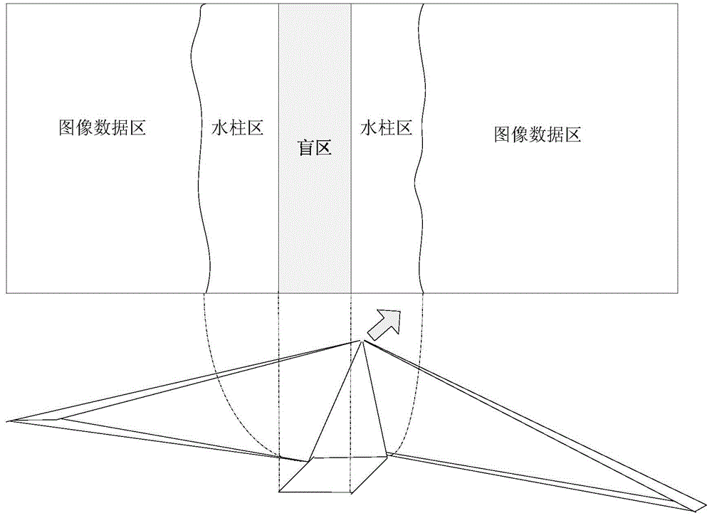
[0033] Combine figure 1 The actual basis of the method for eliminating the slant distance distortion of the multi-beam side-scan sonar image based on the blind zone correction of the present invention is: when the side-scan sonar is traveling, the sonar transmits pulse beams to the bottom of the sea on both sides, and the transducer receives the reverse of the bottom of the sea. The scattered wave is converted into image gray scale according to the echo intensity to form a two-dimensional sonar image. When the first beam returns, the weak echo formed by the water body produces a water column area. However, in actual work, the pulse beam is not vertical When launching downward, but at a certain angle, a blind zone with no data will be generated directly below the sonar, so full consideration should be given to the slope correction. When the sonar is traveling, t...


PUM


Abstract

The invention discloses a multi-beam side-scan sonar slant-distance distortion elimination method based on blind area correction. The method comprises the steps of reading the height to the sea bed and the slant distance from side-scan sonar image and attitude information; calculating the slant distance of a water column area of the side-scan sonar images; calculating the present resolution; calculating the width of the blind area and the width of the water column area at the present resolution; correcting spatial coordinates of pixel points at the left and right portions of the side-scan sonar images; and drawing side-scan sonar images. According to the method, the side-scan sonar blind areas which tend to be neglected in the traditional methods are considered, the image slant-distance distortion can be corrected in a more accurate manner, and the display precision is improved.

Description

Technical field [0001] The invention belongs to the field of side scan sonar data processing, and in particular relates to a method for eliminating slant distance distortion of multi-beam side scan sonar based on blind spot correction. Background technique [0002] Side scan sonar mapping is of great significance for the search of seabed debris and target recognition and positioning. However, due to the mapping principle of side scan sonar and the huge amount of data, the geometric accuracy of sonar images is difficult to reach a high level. Especially the slant-distortion effect of side scan sonar. Slant-distortion leads to the existence of the water column area, which is a direct expression of the width of the water body under the transducer. The wider the water column area, the deeper the water body. The water column area occupies the image space, so that the sonar image is compressed in the part of the image near the water column area. The wider the water column area, the mo...

Claims


Application Information

Patent Timeline
Patent Type & Authority Patents(China)
IPC IPC(8): G01S15/89
CPCG01S7/52G01S15/89
Inventor 叶秀芬李鹏张建国石俭王璘金广王胜邢会明
Owner HARBIN ENG UNIV
Why Eureka
Try Eureka