Organic light-emitting device, manufacturing method thereof, and display device

A technology of organic light-emitting devices and organic light-emitting layers, which is applied in semiconductor/solid-state device manufacturing, semiconductor devices, electric solid-state devices, etc., can solve the problems of low luminous efficiency of the red light layer, and achieve improved luminous efficiency, stability, and stability good sex effect

Active Publication Date: 2020-03-17
KUNSHAN NEW FLAT PANEL DISPLAY TECH CENT +1
View PDF3 Cites 0 Cited by
  • Summary
  • Abstract
  • Description
  • Claims
  • Application Information

AI Technical Summary

Problems solved by technology

[0004] Based on this, it is necessary to solve the problem of low luminous efficiency of the red layer in the existing organic light-emitting devices, and to provide an organic light-emitting device that can improve the luminous efficiency.

Method used


Image

  • Organic light-emitting device, manufacturing method thereof, and display device
  • Organic light-emitting device, manufacturing method thereof, and display device
  • Organic light-emitting device, manufacturing method thereof, and display device

Examples


preparation example Construction

[0099] The invention also provides a preparation method of the organic light-emitting device.

[0100] A method for preparing an organic light-emitting device, comprising the steps of:

[0101] mixing the first host material with the second host material to form a host evaporation source;

[0102] Evaporating the host evaporation source and the guest evaporation source to form the red light layer;

[0103] Wherein, the first host material and the second host material can form an excimer compound.

[0104] The above preparation method can obtain an organic light-emitting device with high luminous efficiency.

[0105] Other steps are all known to those skilled in the art, and will not be repeated here.

[0106] The above preparation method can obtain an organic light-emitting device with high luminous efficiency. In addition, the first host material and the second host material are mixed in advance to form the host material evaporation source. In this way, the number of eva...

Embodiment 1

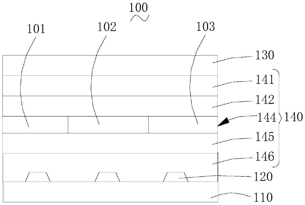
[0112] The glass substrate was cleaned with detergent and deionized water, and dried under an infrared lamp, and a layer of anode material was sputtered on the glass substrate with a film thickness of 150 nm.

[0113] Then, place the glass substrate with the anode material in the vacuum chamber and evacuate to 1×10 -4 Pa, continue to vapor-deposit HATCN on the anode material film layer as a hole injection layer, the film forming rate is 0.1nm / s, and the vapor-deposited film thickness is 20nm. NPB was vapor-deposited on HATCN as a hole transport layer with a film formation rate of 0.1nm / s and a film thickness of 40nm.

[0114] Evaporate the light-emitting layer on the hole transport layer, using the method of double-source co-evaporation, according to the mass percentage of the premixed host material (the first host material and the second host material are mixed in advance) and the phosphorescent dye through the film thickness monitor , adjust the film formation rate to contr...

Embodiment 2~ Embodiment 10

[0124] It is basically the same as Example 1, except that the specific structure of the organic light-emitting device is as follows:

[0125] ITO(150nm) / HATCN(20nm) / NPB(40nm) / premix host material: 1wt%Ir(bt) 3 (30nm) / TPBi(50nm) / 20%Ag: 80%Mg(10nm) / Ag(15nm).

[0126] From Example 2 to Example 10, the ratio of the first host material H12 to the second host material H22 in the premixed host material is 1:9, 1:6, 1:3, 1:2, 1:1 respectively , 2:1, 3:1, 6:1, 9:1.


PUM

PropertyMeasurementUnit
thicknessaaaaaaaaaa
glass transition temperatureaaaaaaaaaa

Abstract

The invention relates to an organic light-emitting device, which includes a red light layer; the red light layer includes a host material and a guest material; the host material includes a first host material and a second host material; the first host material and the second host material can form an excimer compound; The light layer is prepared through the following steps: mixing the first and second host materials to form a host evaporation source; evaporating the host evaporation source and the guest evaporation source to form a red light layer. The organic light-emitting device can reduce the doping concentration of the guest material due to the formation of the exciplex and the FRET energy transfer function, and can improve the stability of the device, improve the luminous efficiency, and effectively avoid the phenomenon of efficiency roll-off. Due to the use of main body premixing, the complexity and cost of the evaporation equipment are reduced, and the difficulty of the evaporation process is reduced at the same time, and the ratio of the first main body material to the second main body material is easy to control, so as to avoid the problem of ratio imbalance. The invention also discloses its preparation method and display device.

Description

technical field [0001] The present invention relates to the field of organic light emitting technology, in particular to an organic light emitting device, a preparation method thereof and a display device. Background technique [0002] Due to its excellent performance, organic light-emitting devices have attracted more and more attention, and are also widely used in various occasions. [0003] In organic light-emitting devices, a single compound is generally selected as the host material of the light-emitting layer for the red light layer. However, a single compound or hole-biased (such as CBP) or electron-biased (such as BAlq), whether it is a hole-biased host material or an electron-biased host material, cannot balance the carriers, resulting in the red light layer The luminous efficiency of organic light-emitting devices decreases. Contents of the invention [0004] Based on this, it is necessary to provide an organic light emitting device capable of improving the lum...

Claims


Application Information

Patent Timeline
Patent Type & Authority Patents(China)
IPC IPC(8): H01L51/50H01L51/56
CPCH10K71/164H10K50/12H10K71/00
Inventor 赵菲李维维闵超罗志忠
Owner KUNSHAN NEW FLAT PANEL DISPLAY TECH CENT
Why Eureka
Try Eureka