Laser infrared composite ground building recognition and navigation method

一种识别方法、建筑物的技术,应用在场景识别、字符和模式识别、电磁波的再辐射等方向,能够解决改进效果限制、目标识别效果不佳、红外成像缺乏距离信息等问题,达到提高识别精确率的效果

Active Publication Date: 2015-04-22
HUAZHONG UNIV OF SCI & TECH
View PDF6 Cites 18 Cited by
  • Summary
  • Abstract
  • Description
  • Claims
  • Application Information

AI Technical Summary

Problems solved by technology

However, infrared imaging lacks distance information and cannot directly obtain 3D information of the target scene, which is not effective for target recognition in complex backgrounds.
In view of this, the existing researches mostly focus on the extraction of building target line features and the multi-level perceptual combination of line features. For example, Jin Taisong, Ye Congying, Li Cuihua et al. ", Computer Engineering, Vol.33 No.6 March 2007 proposed to use the vertical line feature of the building target to find the building target area in the image to improve the accuracy of detection and recognition, but because the infrared image does not contain distance information and target three-dimensional Structural information, the effect of improvement is always limited

Method used


Image

  • Laser infrared composite ground building recognition and navigation method
  • Laser infrared composite ground building recognition and navigation method
  • Laser infrared composite ground building recognition and navigation method

Examples


example 1

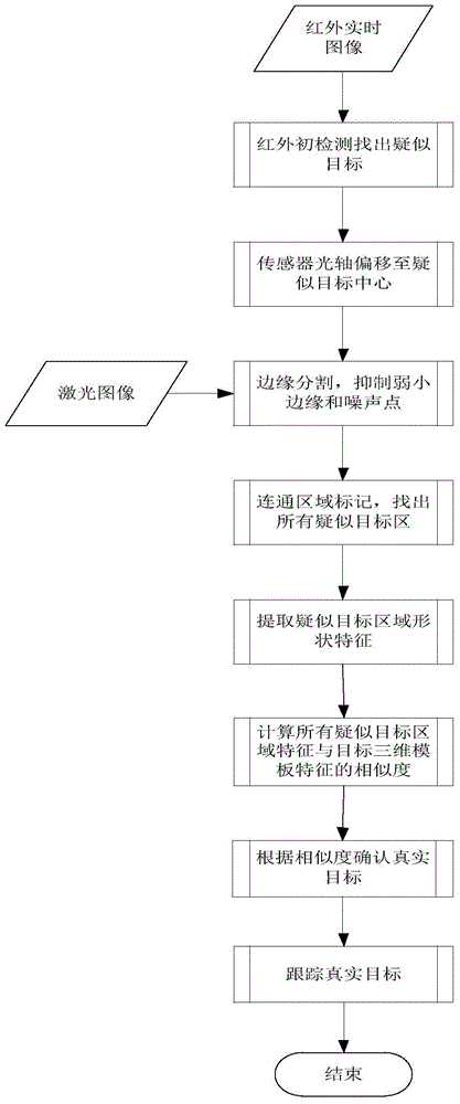
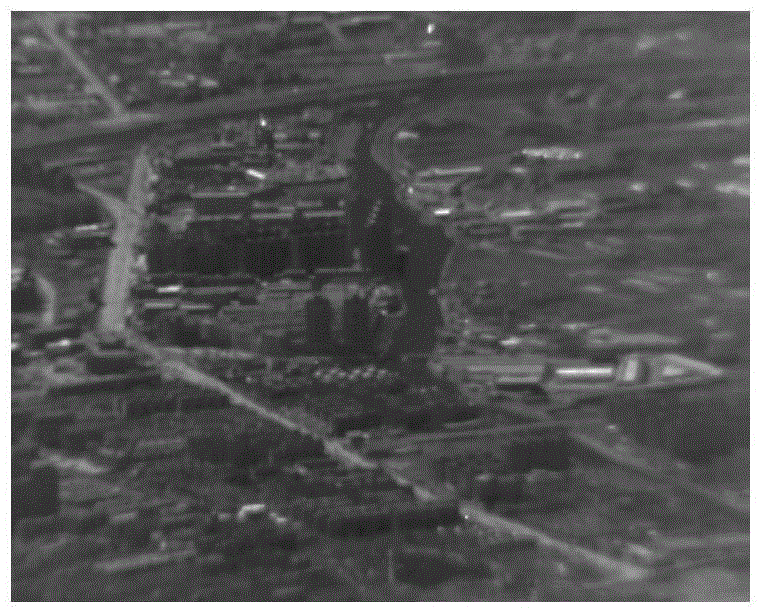
[0050] (1) Aerial ground infrared images.

[0051] The real-time infrared image taken by the aircraft at a pitch angle of 3°, an altitude of 2000 meters, and a distance of 10220 meters from the target is as follows: figure 2 shown.

[0052] (2) Perform detection and positioning in the infrared image to determine the suspected target.

[0053] (2.1) Build a standard feature library

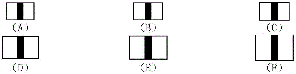
[0054] Make multi-scale target structural elements, target structural elements at different scales such as image 3 shown.

[0055] (2.2) The image enhancement step is to perform histogram equalization on the original input image, which is used to enhance the image contrast with a relatively small dynamic range, and increase the dynamic range of the pixel gray value, thereby obtaining the effect of enhancing the overall contrast of the image.

[0056] (2.3) Morphological background suppression, choose image 3 (A) Pairs of morphological structural elements figure 2 Perform an open operation...

example 2

[0121] As an optimization, the present invention also provides features of infrared imaging suspected target areas, which are fused with shape features of laser imaging suspected target areas to form target matching elements. The feature of the infrared imaging suspected target area is the local contrast of the target potential area. Since the laser image contains the three-dimensional range image of the target's geometric intrinsic information, the laser range image can better reflect the shape characteristics of the target than the infrared image. At the same time, the infrared image can better reflect the gray level difference between the target and the background, so the infrared image can better reflect the local contrast of the target potential area relative to the local interest area than the laser image. Therefore, the present invention fuses the local contrast feature of the target potential area of ​​the infrared imaging suspected target area and the shape feature of...


PUM


Abstract

The invention provides a laser infrared composite ground building recognition and navigation method. The method includes the following steps that (1) a ground infrared image is acquired through aerial photography; (2) the infrared image is detected, so that a suspected target is located and determined; (3) the suspected target is aligned for laser imaging; (4) range gating is conducted on laser imaging so that foreground and background interference can be filtered out; (5) a shape feature of the suspected target is extracted from an image acquired after interference of laser imaging is filtered out, serves as a target matching element and is matched with a target shape feature template, and therefore the target is recognized. By the adoption of the method, laser imaging is fused to infrared imaging target localization, the advantage that the range of infrared imaging is large is used, three-dimensional distance information of laser imaging is adopted, and the locating accuracy of a building is effectively improved.

Description

technical field [0001] The invention belongs to the technical field of imaging automatic target recognition, and in particular relates to a ground building recognition method. Background technique [0002] Buildings are important primitives of man-made targets, and their recognition can be used in urban planning, surveillance, aircraft navigation, collision avoidance and other fields. The ground background is complex, the size and shape of various buildings are different, and the imaging height and imaging angle of the moving platform load are variable, so the identification and positioning of ground buildings is a difficult task. Especially in the navigation guidance of aircraft at night, the pure use of infrared imaging lacks the three-dimensional distance information of the flight scene, and the navigation effect is not good in the background of complex objects. [0003] At present, target recognition is mainly completed through digital processing of infrared imaging. H...

Claims


Application Information

Patent Timeline
Patent Type & Authority Applications(China)
IPC IPC(8): G01S17/88G01S17/18G01S17/86G01S17/89G01S17/933
CPCG01S17/87G01S7/4802G01S17/89G01S17/933G01S17/86G01S17/18G06V20/176
Inventor 张天序药珩姜鹏凡速飞陈一梦马文绚郝龙伟杨智慧
Owner HUAZHONG UNIV OF SCI & TECH
Why Eureka
Try Eureka