Planar waveguide binocular optical display device with saw-toothed sandwich structure

A planar waveguide and optical display technology, applied in optical components, optics, instruments, etc., can solve the problems of complex manufacturing process, uneven brightness of displayed images, small field of view, etc., and achieve simple and easy manufacturing process and easy viewing angle The effect of enlargement and large field of view

Active Publication Date: 2015-04-22
SHANGHAI RAYPAI PHOTONIC CRYSTAL LTD
View PDF7 Cites 21 Cited by
  • Summary
  • Abstract
  • Description
  • Claims
  • Application Information

AI Technical Summary

Problems solved by technology

[0004] In order to solve a series of problems caused by the uneven brightness of the displayed image, small field of view and complex manufacturing process in the traditional wearable display optical system, the present invention designs a planar waveguide binocular optical display device with a sawtooth sandwich structure

Method used


Image

  • Planar waveguide binocular optical display device with saw-toothed sandwich structure
  • Planar waveguide binocular optical display device with saw-toothed sandwich structure
  • Planar waveguide binocular optical display device with saw-toothed sandwich structure

Examples


Embodiment Construction

[0028] Below in conjunction with accompanying drawing, specific working process of the present invention is given description.

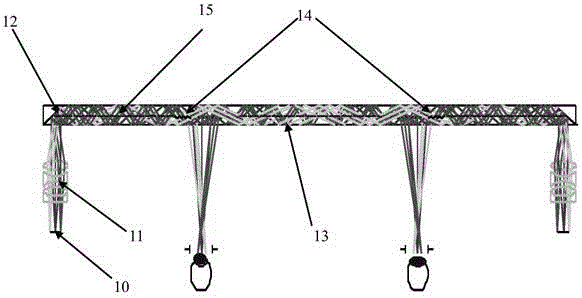
[0029] figure 1 It is a schematic diagram of a planar waveguide binocular optical display device with a sawtooth sandwich structure according to the present invention. Such as figure 1 As shown, the system composition of the optical display device of the present invention includes: an image display light source 10 , a collimating lens group 11 , a coupling input surface 12 , a planar waveguide substrate 13 , a sawtooth groove structure 14 , and a half light splitting structure 15 . The light from the image display light source 10 is collimated by the collimating lens group 11 and then enters the coupling-in surface 12 , and enters the planar waveguide substrate 13 after being reflected by the coupling surface. After the light is transmitted without loss in the planar waveguide substrate to the position where the display output is required, since th...


PUM


Abstract

The invention provides a planar waveguide binocular optical display device with a saw-toothed sandwich structure. The planar waveguide binocular optical display device comprises an image display light source, a collimating lens group, a coupling input surface, a planar waveguide substrate, a saw-toothed groove structure and a one-half light-split structure, wherein the image display light source is used for emitting display light waves for displaying a required image; a collimating lens is used for collimating the light waves of the light source; the coupling input surface is used for coupling the collimated light waves into a planar waveguide; the planar waveguide substrate is used for carrying out total reflection diffusion on the coupled light waves; the saw-toothed groove structure is used for expanding a view field and outputting the coupled light waves to the substrate; and the one-half light-split structure is used for uniformly distributing rays and improving the brightness uniformity of the image. The planar waveguide binocular optical display device has the characteristics of uniform image brightness, light and thin structure, easily-expanded view field angle, simple processing technology and low cost, not only can be used for wearable display, but also can be used for field real-time training simulation, naked-eye 3D display, searching and locating, fact display and the like.

Description

technical field [0001] The invention relates to a planar waveguide optical display device, in particular to a planar waveguide binocular optical display device with a sawtooth sandwich structure that can be used for full-eye wearable penetrating display. Background technique [0002] For head-mounted display optical systems, in order to reflect the effect of augmented reality, optical components are usually used to virtually display image information at a certain distance in front of the human eye, so that the wearer can observe the surrounding scenery while browsing the information. change so as not to affect normal behavior. For this reason, the wearable display optical system of augmented reality, in order to enable the wearer to obtain all the information from the display light source in time, usually requires the display system to have the characteristics of large field of view, light and thin structure, and uniform image brightness within the field of view. The tradit...

Claims


Application Information

Patent Timeline
Patent Type & Authority Applications(China)
IPC IPC(8): G02B27/01
CPCG02B27/0101G02B27/0172G02B2027/0132
Inventor 张圣军张庆
Owner SHANGHAI RAYPAI PHOTONIC CRYSTAL LTD
Why Eureka
Try Eureka