
On-line Time Meter for Fuze Clock Mechanism

A clock mechanism and time measuring instrument technology, applied in clocks, time interval measurement devices, electromechanical unknown time interval measurement, etc., can solve the problem of lack of accuracy and repeatability, hidden dangers in product quality, and failure to guarantee the quality of military products and other problems, to achieve the effect of convenient operation, solving test problems, and low cost

Active Publication Date: 2017-02-22
JIANGJI MINKE IND COMPANY LIMITED JILIN CITY
View PDF6 Cites 0 Cited by
  • Summary
  • Abstract
  • Description
  • Claims
  • Application Information

AI Technical Summary

Problems solved by technology

[0002] The time test of the fuze clock mechanism, according to the technical requirements of the National Military Standard GJB165.6A-2004 (K) Part 6 "Testing Mechanism of the Fuze Clock Mechanism under Static Conditions", has strict regulations on the time measuring equipment, but so far, there are still There is no one stereotyped time measuring instrument available for use. Various scientific research and production units design their own, and there are all kinds of them. Some units even use manual visual inspection and stopwatch timing. The accuracy and repeatability are not up to the national military standard GJB165.6A- The technical requirements of 2004(K) cannot guarantee the quality of military products
In addition, at present there is no one that meets the technical requirements of the national military standard GJB165.6A-2004 (K), which can be used not only for laboratory sampling tests, but also for online time measuring instruments for fuze clock mechanisms that can be used for 100% detection on production lines. Leaving hidden dangers to product quality

Method used


Image

  • On-line Time Meter for Fuze Clock Mechanism
  • On-line Time Meter for Fuze Clock Mechanism

Examples


Embodiment Construction

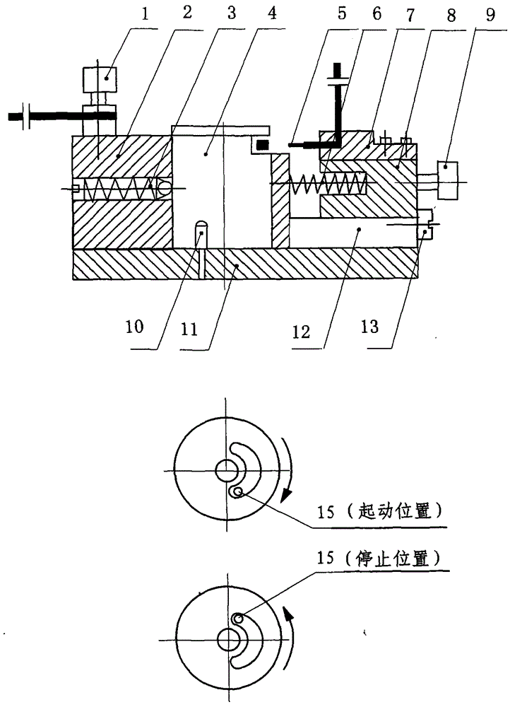
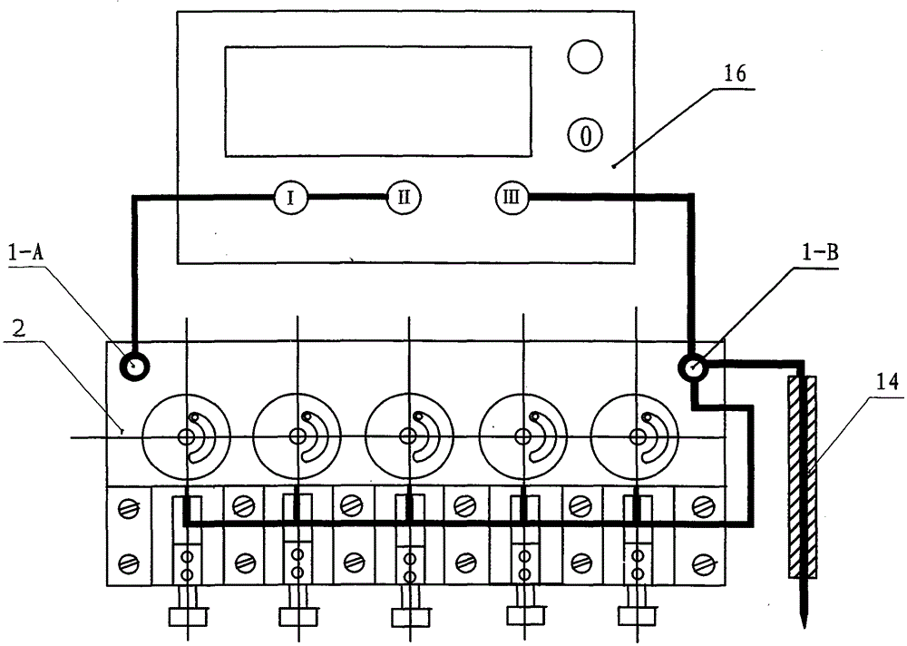
[0016] Below in conjunction with the accompanying drawings and embodiments for further description, a fuze watch mechanism on-line time measuring instrument, it is composed of a signal conversion device and a digital electric stopwatch, the signal conversion device includes: the first terminal 1-A, the second terminal 1 -B, main body 2, compression spring 3, clock mechanism 4, electrode 5, return spring 6, clamp block 7, slider 8, handle 9, positioning rod 10, bottom plate 11, slider guide plate 12, limit screw 13 and dial needle 14, its connection relation is: described clock mechanism 4 is put into the station of described main body 2, utilizes the original positioning hole of described clock mechanism 4 bottom, inserts described base 11 It is positioned in the positioning rod 10, and is compressed by the compression spring 3, and now the clock mechanism 4 is ready for installation and enters the waiting state;

[0017] The electrode (5) is fixed on the clamp block (7), the ...


PUM


Abstract

The invention belongs to the field of metering technology instruments and meters, and relates to an online time measuring instrument of a fuse clock mechanism. The online time measuring instrument is composed of a signal converting device and a digital electric second meter. The signal converting device comprises a first binding post 1-A, a second binding post 1-B, a main body 2, a compression spring 3, the clock mechanism 4, an electrode 5, a reset spring 6, a clamping block 7, a sliding block 8, a handle 9, a positioning rod 10, a bottom plate 11, a sliding block guiding plate 12, a limiting screw 13, a teasing needle 14 and the like. The digital electric second meter is adopted for delay measurement. In the circuit selection, an on-off-on synchronous starting and synchronous stopping circuit is selected, various technical indexes confirm to the stipulation of the sixth part of A Fuse Clock Mechanism Static Test Mechanism GJB165.6A-2004(K), the online time measuring instrument not only can be used for the sampling test of a test room and is mainly used for carrying out 100% of delay detection on the clock mechanism online, and the product quality is ensured. The accuracy of the online time measuring instrument is higher than the accuracy stipulated by the standard, the indicating value is stable, the inspecting efficiency is high, and one product can be detected for not more than 10 seconds.

Description

technical field [0001] The on-line time measuring instrument for fuze clock mechanism belongs to the field of metering technology instruments and meters, and is mainly used for online delay time testing of fuze clock mechanism. Background technique [0002] The time test of the fuze clock mechanism, according to the technical requirements of the National Military Standard GJB165.6A-2004 (K) Part 6 "Testing Mechanism of the Fuze Clock Mechanism under Static Conditions", has strict regulations on the time measuring equipment, but so far, there are still There is no one stereotyped time measuring instrument available for use. Various scientific research and production units design their own, and there are all kinds of them. Some units even use manual visual inspection and stopwatch timing. The accuracy and repeatability are not up to the national military standard GJB165.6A- The technical requirements of 2004(K) cannot guarantee the quality of military products. In addition, a...

Claims


Application Information

Patent Timeline
Patent Type & Authority Patents(China)
IPC IPC(8): G04F8/00
Inventor 刘延中徐长江许胜陈东林周凤云刘文异练绵华
Owner JIANGJI MINKE IND COMPANY LIMITED JILIN CITY
Learn More