Radial diffuser with groove structure and design method of radial diffuser

A radial guide vane and design method technology, which is applied in the field of centrifugal pumps, can solve the problems that the slotted structure of the radial guide vane blade has not been reported, and achieve the effects of simple structure, improved flow capacity, and strong practicability

Inactive Publication Date: 2015-04-22
JIANGSU UNIV
View PDF3 Cites 7 Cited by
  • Summary
  • Abstract
  • Description
  • Claims
  • Application Information

AI Technical Summary

Problems solved by technology

[0004] However, in terms of improving the internal flow of the guide vane in the radial guide vane centrifugal pump, there is no report on the patent of the slotted structure and design of the radial guide vane blade

Method used


Image

  • Radial diffuser with groove structure and design method of radial diffuser
  • Radial diffuser with groove structure and design method of radial diffuser
  • Radial diffuser with groove structure and design method of radial diffuser

Examples


Embodiment 1

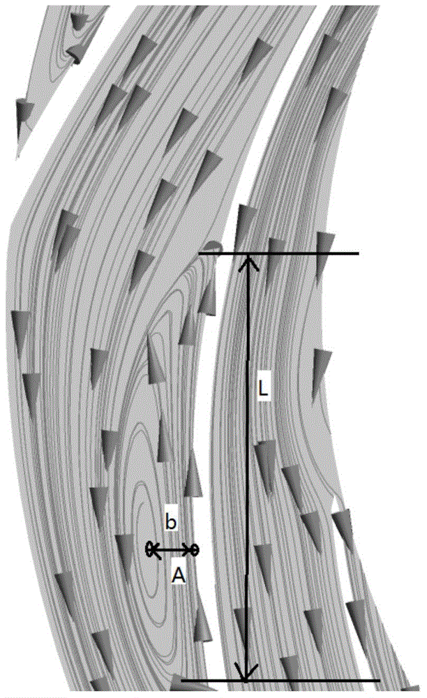
[0031] Using the computational fluid dynamics software ANSYS CFX 14.5 to simulate the radial guide vanes of the multistage centrifugal pump with constant values, obtain the velocity streamline distribution diagram of all flow channels in the guide vane, read the velocity streamline distribution diagram and mark the velocity streamlines The number, position, length L and flow direction of the vortex in the distribution diagram, thereby determine the number, position, size and direction of the groove 4, slot 4 on the radial guide vane, and obtain the grooved 4 radial guide vanes.

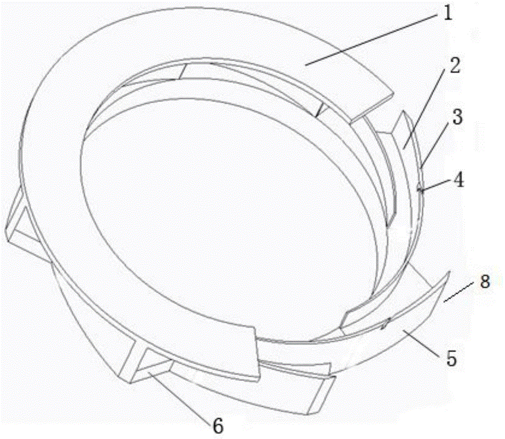
[0032] Such as figure 1 As shown, the radial guide vane with groove 4 includes a front shroud 1 , a blade 3 and a rear shroud 6 , and the groove 4 communicates with the working surface 5 of the blade and the back surface 2 of the blade. Because there are 8 vortex areas in the radial guide vane velocity streamline distribution diagram of the multistage centrifugal pump, and the vortex areas occur on t...

Embodiment 2

[0035] Using the computational fluid dynamics software ANSYS CFX 14.5 to conduct constant numerical simulation on the radial guide vane of the single-stage centrifugal pump, obtain the velocity streamline distribution diagram of all flow channels in the guide vane, read the velocity streamline distribution diagram and mark the velocity streamline The number, position, length L and flow direction of the vortex in the distribution diagram, thereby determine the number, position, size and direction of the groove 4, slot 4 on the radial guide vane, and obtain the grooved 4 radial guide vanes.

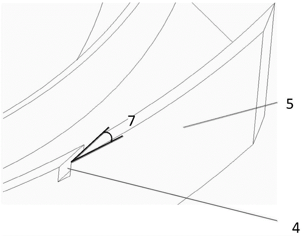
[0036] Because there are 5 vortex regions in the radial guide vane, and the vortex regions occur on the working surface of the blades and close to the blade outlet 8, five slots 4 are opened on the 5 blades 3 where the vortex regions appear. The groove 4 is close to the front cover plate 1 and is located at 1 / 4 of the blade length from the blade outlet 8; the included angle 7 is 25°, and th...


PUM


Abstract

The invention provides a radial diffuser with a groove structure and a design method of the radial diffuser. The radial diffuser comprises a front cover plate, blades, grooves and a rear cover plate. Blade working faces and blade rear faces are communicated through the grooves. Fixed constant numerical simulation is conduced on the radial diffuser through computational fluid mechanics software ANSYS CFX 14.5, a speed flow line distribution diagram of all passageways in the radial diffuser is acquired, and then the radial diffuser with the grooves is designed. Numerical stimulation is conducted on the radial diffuser with the grooves, the speed flow line distribution diagram of the radial diffuser is acquired, whether the grooves are improved or not is analyzed, and if the grooves are not obviously improved, the grooves are improved according to the speed flow line distribution diagram again till the effect is obvious. The vortex region of the working face of the radial diffuser is reduced, the internal flow field distribution of the radial diffuser is improved, and therefore the discharge capacity of the radial diffuser is improved. The radial diffuser with the groove structure is simple in structure, the groove structure can be designed in the radial diffuser mold manufacturing process, and high practicality is achieved.

Description

technical field [0001] The invention belongs to the field of centrifugal pumps, in particular to a radial guide vane with grooved structure and a design method thereof. Background technique [0002] The radial guide vane is located between the impeller and the volute. It is widely used in the guide vane single-stage centrifugal pump in the field of nuclear power pumps. The radial guide vane converts the kinetic energy of the high-energy fluid obtained from the impeller into pressure energy, reducing the impact of the fluid The impact force of the volute is also used in multi-stage centrifugal pumps in the field of seawater desalination. The radial guide vane reduces the velocity of the fluid, which can eliminate the velocity circulation of the fluid, so that the hydraulic loss will be reduced when the fluid enters the next stage of the impeller. . However, there are very complex flow characteristics in the guide vane, such as secondary flow, flow diversion, etc., resulting ...

Claims


Application Information

Patent Timeline
Patent Type & Authority Applications(China)
IPC IPC(8): G06F17/50F04D29/44
Inventor 王文杰袁寿其裴吉张金凤孟凡陈佳
Owner JIANGSU UNIV
Why Eureka
Try Eureka