
Multi-phase permanent magnet direct current motor

A permanent magnet DC, multi-phase technology, applied in motors, synchronous motors with stationary armatures and rotating magnets, electric vehicles, etc., can solve problems such as harmonic heating, output torque imbalance of permanent magnet DC motors, etc. Achieve the effect of small starting current, low modification cost and simple control equipment

Inactive Publication Date: 2015-04-22
TAIYUAN UNIV OF TECH
View PDF6 Cites 3 Cited by
  • Summary
  • Abstract
  • Description
  • Claims
  • Application Information

AI Technical Summary

Problems solved by technology

[0003] The invention solves the problems of unbalanced output torque and serious harmonic heating of existing permanent magnet DC motors, and provides a multi-phase permanent magnet DC motor

Method used


Image

  • Multi-phase permanent magnet direct current motor
  • Multi-phase permanent magnet direct current motor
  • Multi-phase permanent magnet direct current motor

Examples


Embodiment Construction

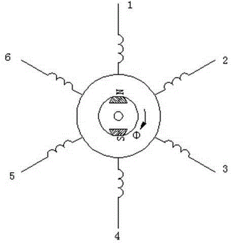
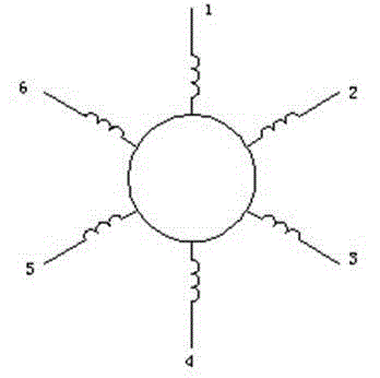
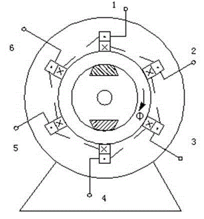
[0010] The multi-phase permanent magnet DC motor is composed of a stator, a rotor and a power supply device; the magnetic poles of the rotor are permanent magnet poles made of ferrite or rare earth permanent magnet materials; the stator has 12 np slots, n=1 / 2, 1 , 2, 3..., p is the number of pole pairs (that is, there are 12n slots under each pole pair of the stator), and each pole pair of the stator is provided with six-phase windings with symmetrical distribution and equal turns, with different pole pairs The lower in-phase windings are connected in series or in parallel, and the outlet ends of the phase windings are connected to each other; the power supply device continuously supplies power to the stator windings according to the position and speed of the rotor in the following order: the inlet ends of the first phase winding are positive and the fourth The incoming end of the phase winding is negative, the incoming end of the second phase winding is positive, the incoming e...


PUM


Abstract

The invention relates to a permanent magnet direct current motor, in particular to a multi-phase permanent magnet direct current motor. The problems that in an existing permanent magnet direct current motor, output torque is imbalanced, and harmonic wave heating is serious are solved. 12*n grooves are formed under each pair of poles of a stator of the multi-phase permanent magnet direct current motor, wherein n is equal to 1 / 2, 1, 2, 3..., six phases of windings with the same number of turns are symmetrically arranged under each pole pair of the stator, and the wire outlet ends of all phases of windings are connected; a power supply device enables direct current to pass through (1-4), (2-5), (3-6), (4-1), (5-2) and (6-3) in sequence to penetrate through the windings according to the rotor position and rotating speed, the motor stator windings will produce a clockwise rotation magnetic field in an air gap, and under the drive of the magnetic field, a rotor of the motor will also rotate clockwise. The motor can be widely used in the variable-speed variable-shaft-power nonconstant speed using environment such as an electromobile, an elevator, a belt conveyer and a ship, and can also be applied to large-power large-starting-torque speed adjusting equipment such as petroleum and spinning high-precision devices.

Description

Technical field [0001] The invention relates to a permanent magnet DC motor, in particular to a multi-phase permanent magnet DC motor. Background technique [0002] The rotor of the existing permanent magnet DC motor is a permanent magnet, and the stator has a slotted lower winding. The stator windings are symmetrical windings arranged in three phases, connected to a Y-shaped connection. In this way, when each phase is turned on, the other two phases must be turned on respectively in turn as the current outlet. However, the switching of the current between phases may easily cause current discontinuity or impact, resulting in unbalanced output torque of the motor, serious harmonic heating of the stator and rotor, and reverse breakdown of the power switch tube in the power supply device. Summary of the invention [0003] The invention solves the problems of unbalanced output torque of the existing permanent magnet DC motor and serious harmonic heating, and provides a multi-phase p...

Claims


Application Information

Patent Timeline
Patent Type & Authority Applications(China)
IPC IPC(8): H02K21/14H02K3/28
CPCH02K3/28H02K21/14Y02T10/64
Inventor 程开业童国力秦文萍
Owner TAIYUAN UNIV OF TECH
Learn More