Boost type DC-DC converter synchronous power tube current limiting circuit

A DC-DC, synchronous power technology, applied in the direction of output power conversion devices, electrical components, etc., can solve problems such as damage to power tubes

Inactive Publication Date: 2015-04-22
CHANGAN UNIV
View PDF5 Cites 10 Cited by
  • Summary
  • Abstract
  • Description
  • Claims
  • Application Information

AI Technical Summary

Problems solved by technology

However, the Boost circuit is input directly through the synchronous power transistor Q in the start-up phase 1 Charge the output and synchronize the power transistor Q 1 To face a large inrush current, and if the synchronous power tube Q 1 Turn on the main switch Q when the current is large 2 , there is a risk of damaging the power tube

Method used


Image

  • Boost type DC-DC converter synchronous power tube current limiting circuit
  • Boost type DC-DC converter synchronous power tube current limiting circuit
  • Boost type DC-DC converter synchronous power tube current limiting circuit

Examples


Embodiment 1

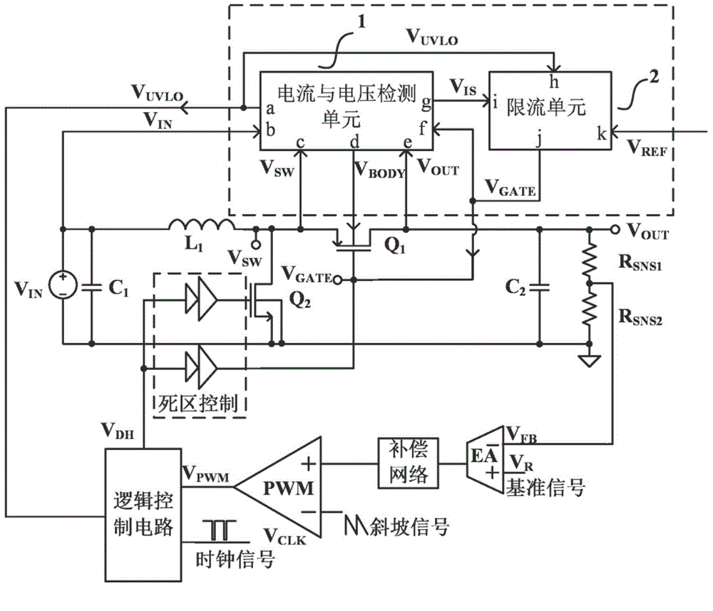
[0056] refer to figure 2 , the Boost type DC-DC converter synchronous power tube current limiting circuit of the present invention includes a current and voltage detection unit 1 and a current limiting unit 1 .

[0057] The voltage and current detection unit 1 is provided with four input terminals b, c, e, f and three output terminals a, d, g; the current limiting unit 2 is provided with three input terminals h, i, k and a Output terminal j; where the first input terminal b of the voltage and current detection unit 1 is connected to the input voltage V IN ; The second input terminal c, the third input terminal f and the fourth input terminal e are respectively connected to the synchronous power transistor Q 1 The source, gate and drain of the switch node voltage V SW , gate control signal V GATE and the output voltage V OUT ; Wherein the first output terminal a outputs the undervoltage control signal V UVLO To the undervoltage control terminal of the logic control circui...

Embodiment 2

[0079] The current and voltage detection unit 1 of this embodiment is the same as that of the first embodiment.

[0080] refer to Figure 5 , the current limiting unit 2 of the present embodiment includes an inverter 201, a current source I S1 , PMOS tube M 201 , PMOS tube M 202 , PMOS tube M 203 , PMOS tube M 204 , PMOS tube M 207 , PMOS tube M 208 , PMOS tube M 211 , NMOS tube M 205 , NMOS tube M 206 , NMOS tube M 209 , NMOS tube M 210 and NMOS tube M 212 ;in:

[0081] The current source I S1 , whose input terminal is connected to the internal power supply V DD , whose output terminal is connected to the PMOS tube M 201 and M 202 on the source;

[0082] The PMOS tube M 201 The gate and current sampling signal V IS Connected, and its drains are respectively connected to the NMOS transistor M 206 The drain and NMOS transistor M 205 The source is connected; PMOS tube M 202 gate with an external reference voltage V REF Connected, and its drains are respect...

Embodiment 3

[0090] The current limiting unit 2 in this embodiment is the same as that in Embodiment 1.

[0091] refer to Image 6 , the current and voltage detection unit 1 of the present embodiment includes an inverter 101, an inverter 102, a current source 1 S1 , the first resistor R 1 , the second resistance R 2 , the third resistor R 3 , the fourth resistor R 4 , the fifth resistor R 5 , the first diode D 1 , the second diode D 2 , the first capacitance C 1 , Power mirror PMOS tube M 115 , PMOS tube M 101 , PMOS tube M 103 , PMOS tube M 105 , PMOS tube M 111 , PMOS tube M 113 , PMOS tube M 116 , PMOS tube M 117 , PMOS tube M 118 , NMOS tube M 102 , NMOS tube M 104 , NMOS tube M 106 , NMOS tube M 107 , NMOS tube M 108 , NMOS tube M 109 , NMOS tube M 110 , NMOS tube M 112 and NMOS tube M 114 . in:

[0092] The current source I S1 , whose input terminal is connected to the internal power supply V DD , whose output terminal is connected to the NMOS tube M 107...


PUM


Abstract

The invention provides a boost type DC-DC converter synchronous power tube current limiting circuit for solving the problem that the risk of damaging a main switching tube Q2, a synchronous power tube Q1 and output end equipment exists when surge current is started in an existing Boost circuit. The circuit can achieve the function of limiting the current of the synchronous power tube Q1. The whole boost type DC-DC converter synchronous power tube current limiting circuit is simple in structure, high in precision, fast in response and capable of improving the reliability of a system.

Description

technical field [0001] The invention belongs to the technical field of electronic circuits, and relates to an analog integrated circuit, in particular to a current-limiting circuit for a synchronous power tube of a Boost DC-DC converter. Background technique [0002] With the rapid development of semiconductor technology and the continuous expansion of application fields, Boost circuits convert low DC voltages into high DC voltages to boost DC voltages. Therefore, Boost circuits are widely used in daily life. The boost circuit is generally composed of a control circuit, a switch tube, an energy storage element inductor, and a capacitor. Its step-up process is an inductive energy transfer process. When charging, the inductor absorbs energy, and when discharging, the inductor releases energy. [0003] The system structure of a typical synchronous Boost DC-DC converter is as follows figure 1 shown. The circuit uses a voltage negative feedback loop controlled by a pulse widt...

Claims


Application Information

Patent Timeline
Patent Type & Authority Applications(China)
IPC IPC(8): H02M1/32
CPCH02M1/32
Inventor 李演明张豪邱彦章吴凯凯杨晓冰文常保
Owner CHANGAN UNIV
Why Eureka
Try Eureka