Space laser communication terminal level system testing method

A technology of laser communication and system testing, which is applied in the direction of transmission monitoring/testing/fault measurement systems, etc., and can solve problems such as short-distance and terminal-level system testing that have not yet been realized

Inactive Publication Date: 2015-04-22
PEKING UNIV
View PDF4 Cites 13 Cited by
  • Summary
  • Abstract
  • Description
  • Claims
  • Application Information

AI Technical Summary

Problems solved by technology

[0006] To sum up, the existing space laser communication ground verification and testing technology methods have not yet realized the short-distance, terminal-level system test, that is, the short-distance direct terminal-to-computer alignment performance test

Method used


Image

  • Space laser communication terminal level system testing method
  • Space laser communication terminal level system testing method
  • Space laser communication terminal level system testing method

Examples


Embodiment Construction

[0078] Below in conjunction with accompanying drawing, further describe the present invention through embodiment, but do not limit the scope of the present invention in any way.

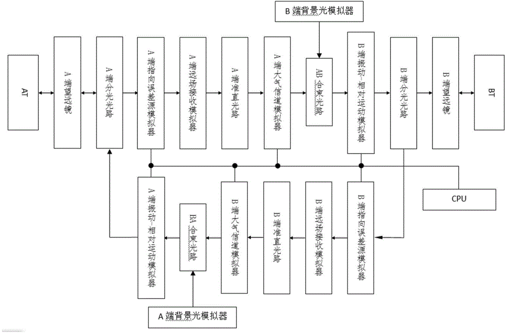
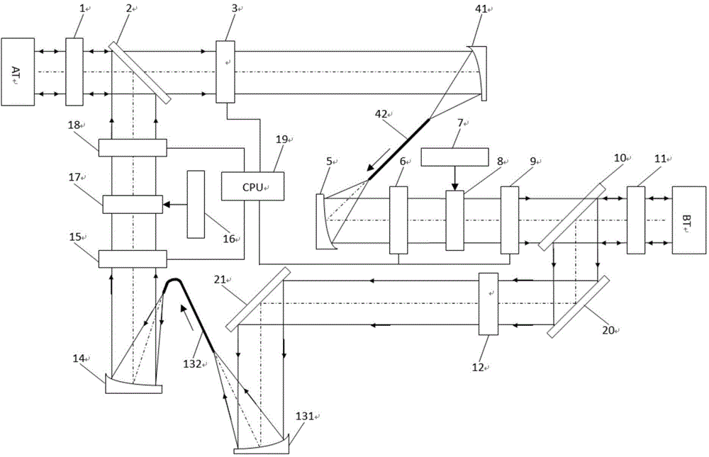
[0079] figure 1 It is an overall flow chart of the present invention, and the structure of the present embodiment is as follows figure 2 As shown, it includes A-end telescope 1, A-end splitting optical path 2, A-end pointing error source simulator 3, A-end far-field receiving simulator 4, A-end collimating optical path 5, A-end atmospheric channel simulator 6, and B-end Background light simulator 7, AB beam combining optical path 8, B-end vibration-relative motion simulator 9, B-end splitting optical path 10, B-end telescope 11, B-end pointing error source simulator 12, B-end far-field receiving simulator 13 , B-end collimation optical path 14, B-end atmospheric channel simulator 15, A-end background light simulator 16, BA beam combining optical path 17, A-end vibration-relative motion simulator 18...


PUM


Abstract

The invention discloses a space laser communication terminal level system testing method. Light beams are emitted from a tested terminal, pass through a telescope, a light-splitting optical path, a pointing error source simulator, a far-field receiving simulator, a collimation optical path and an atmospheric channel simulator in sequence, and are combined with light beams from a background light simulator through a beam-combining optical path. The combined light beams pass through a vibration-relative motion simulator, the light-splitting optical path and the telescope in sequence, and are received by an opposite-side tested terminal. Through adoption of the method, space laser communication terminal level system testing, including tracking and pointing characteristics (including tracking and pointing accuracy and tracking and pointing bandwidth), capturing characteristics (including capturing time and capturing probability), communication characteristics (including bit error rate and detection sensitivity) and the like are realized. The structure occupies a small space. Two communication terminals can perform terminal level system testing of multi-parameter direct alignment performance at a close range, and a plurality of external factors influencing space laser communication performance are simulated. The measuring accuracy is high.

Description

technical field [0001] The invention relates to the field of space laser communication, in particular to a test method for a space laser communication terminal machine-level system. Background technique [0002] As a payload, the space laser communication system must be strictly tested for its main technical indicators and performance parameters, such as tracking and targeting accuracy, acquisition characteristics, and communication error codes, no matter after the development is completed or before launch. rate etc. Generally, the distance of space laser communication is hundreds of kilometers to hundreds of thousands of kilometers, or even farther, while the diameter of optical transceivers is several centimeters to tens of centimeters, so the reception of optical signals is far-field reception. The space laser communication ground test can be divided into system level test, subsystem or module level test and component level test. The transmitting terminal and the receiv...

Claims


Application Information

Patent Timeline
Patent Type & Authority Applications(China)
IPC IPC(8): H04B10/07
Inventor 王建民
Owner PEKING UNIV
Why Eureka
Try Eureka