led dimming drive circuit

A dimming drive and circuit technology, applied in the field of lighting, can solve problems such as no technical inspiration, achieve the effects of improving reliability and safety, enhancing the ability to resist electromagnetic disturbance, and improving utilization efficiency

Active Publication Date: 2017-11-17
SICHUAN SUNFOR LIGHT
View PDF6 Cites 3 Cited by
  • Summary
  • Abstract
  • Description
  • Claims
  • Application Information

AI Technical Summary

Problems solved by technology

Therefore, the aforementioned reference documents have no technical inspiration to the present invention

Method used


Image

  • led dimming drive circuit
  • led dimming drive circuit
  • led dimming drive circuit

Examples


Embodiment Construction

[0063] In order to make the object, technical solution and advantages of the present invention clearer, the present invention will be described in further detail below with reference to the accompanying drawings and preferred embodiments. However, it should be noted that many of the details listed in the specification are only for readers to have a thorough understanding of one or more aspects of the present invention, and these aspects of the present invention can be implemented even without these specific details.

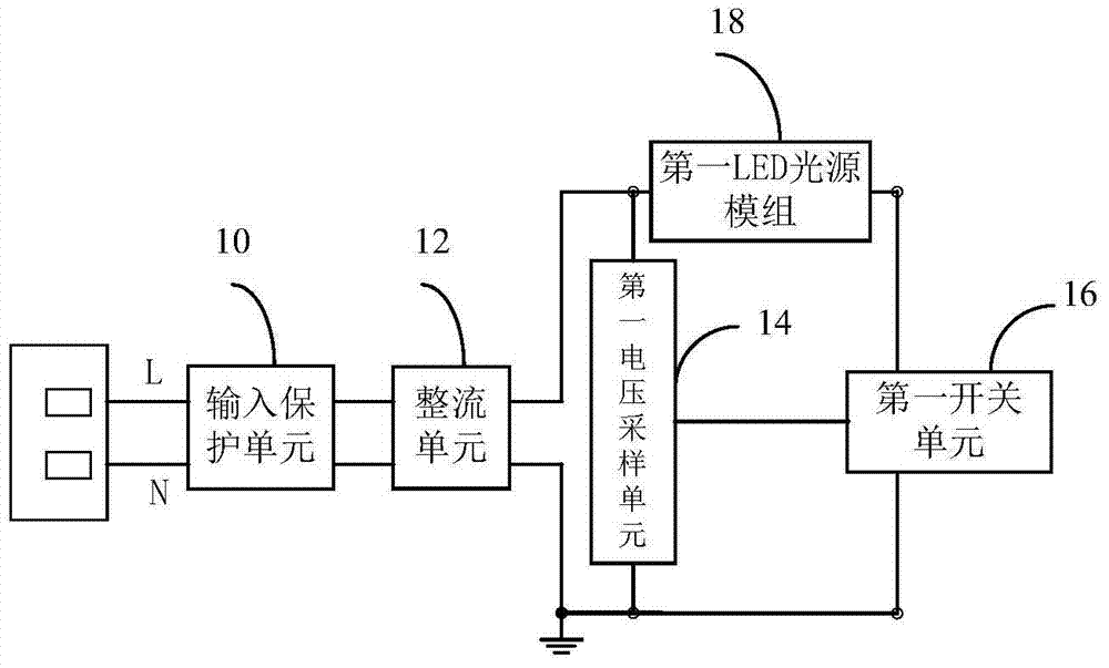
[0064] figure 1 A schematic diagram showing the principle of an AC dimming drive circuit for LEDs according to an embodiment of the present invention. Such as figure 1 As shown, the AC dimming driving circuit includes a rectifying unit 12 , a first voltage sampling unit 14 , a first switching unit 16 and a first LED light source module 18 . The rectification unit 12 includes four diodes, and the four diodes form a bridge rectification circuit. Alternatively, t...


PUM


Abstract

The invention relates to an LED dimming driving circuit, which includes a rectifying unit and an N-level LED direct current driving circuit. Wherein, the i-th LED DC drive circuit is composed of an i-th voltage sampling unit, an i-th switching unit and an i-th LED light source module. N is a natural number, i=1,2,3,...,N; the first end of the i-th voltage sampling unit and the input end of the i-th LED light source module are jointly connected to the first output end of the rectification unit when i is 1 , when i is not 1, they are commonly connected to the output end of the i‑1th LED light source module. The second end of the i-th voltage sampling unit is grounded, and the voltage dividing end of the i-th voltage sampling unit is connected to the second input end of the i-th switch unit. The first input end of the i-th switch unit is connected to the output end of the i-th LED light source module, and the output end of the i-th switch unit and the second output end of the rectification unit are grounded. The invention is compatible with traditional thyristor dimmers, and realizes adjustment of brightness, color temperature or color without separate wiring.

Description

[0001] The present invention is a divisional application of the original application number 201210424253.2, the original application date is October 30, 2012, and the original invention title is a dimming drive circuit for alternating current direct drive LED modules. technical field [0002] The invention relates to the lighting field, in particular to an LED dimming drive circuit compatible with a thyristor dimmer. Background technique [0003] As a new type of solid-state light source, LED is expected to become a new generation of lighting source due to its advantages of energy saving, environmental protection and long life. As we all know, LED is driven by DC voltage, but our production and living electricity is AC cycle power. Therefore, in order to light up the LED normally, a power converter is needed to realize the functions of rectification and step-down. The introduction of power converters brings many negative effects. First, the life of the power converter is m...

Claims


Application Information

Patent Timeline
Patent Type & Authority Patents(China)
IPC IPC(8): H05B37/02
Inventor 李东明龙文涛封正勇杨冕
Owner SICHUAN SUNFOR LIGHT
Why Eureka
Try Eureka