Electrically operable holding brake system for a pneumatic braking installation and method for operating an electrically operable holding brake system

A brake system and pneumatic brake technology, which is applied to brake transmissions, brakes, vehicle components, etc., can solve problems such as difficult manufacturing and complex structure of the parking brake system

Inactive Publication Date: 2015-04-22
KNORR-BREMSE SYST FUER NUTZFAHRZEUGE GMBH
View PDF5 Cites 5 Cited by
  • Summary
  • Abstract
  • Description
  • Claims
  • Application Information

AI Technical Summary

Problems solved by technology

Accordingly, known electrically operable parking brake systems are complex in construction and difficult to manufacture

Method used


Image

  • Electrically operable holding brake system for a pneumatic braking installation and method for operating an electrically operable holding brake system
  • Electrically operable holding brake system for a pneumatic braking installation and method for operating an electrically operable holding brake system
  • Electrically operable holding brake system for a pneumatic braking installation and method for operating an electrically operable holding brake system

Examples


Embodiment Construction

[0039] In the drawings, the same reference numerals denote the same or similar components.

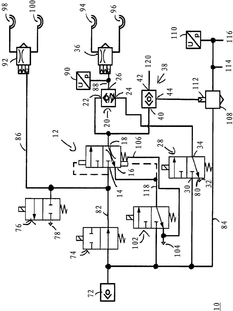
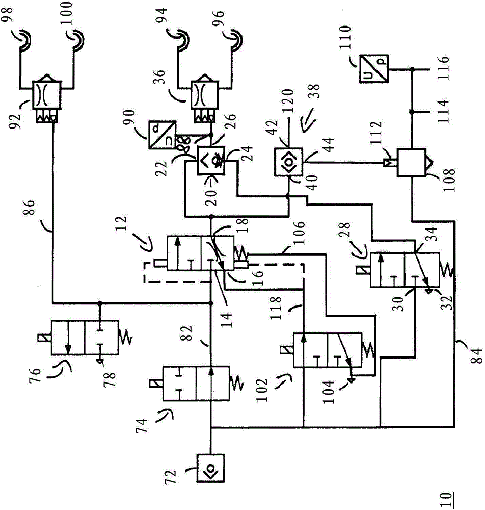
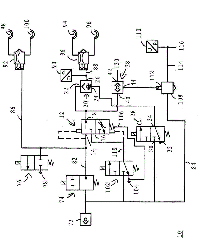
[0040] figure 1 The electrically actuated parking brake system is shown in a first switching position. exist figure 1 The electrically operable parking brake system 10 shown in may comprise a control valve device 12 and / or a directional valve 38 and / or a further directional valve 20 and / or a valve device 28 and / or a supply valve 74 and / or a vent valve 76 and / or a control and vent valve arrangement 102 . The valve device 28 and / or the supply valve 74 and / or the outlet valve 76 and / or the control and outlet valve device 102 can be designed as electrically actuatable solenoid valves, for example. The supply valve 74 can be configured, for example, as an electrically actuable 2 / 2-way valve and can comprise a resilient element, such as a spring, which can define a rest position of the supply valve 74 . The rest position of the supply valve 74 may correspond, for example, to the figure ...


PUM


Abstract

The invention relates to an electrically operable holding brake system (10) for a pneumatic braking installation, having a control valve device (12) which comprises a first control valve input connection (14), a second control valve input connection (16) and a control valve output connection (18), a supply valve (74) coupled to the first control valve input connection (14), and a control and vent valve device (102) coupled to the second control valve input connection (16). According to the invention, the control valve output connection (18) is coupled directly to a first shuttle valve input connection (40) of a shuttle valve (38), and a shuttle valve output connection (44) of the shuttle valve (38) is coupled to a relay control input (112) of a relay valve (108). The invention also relates to a method for operating an electrically operable holding brake system (10).

Description

technical field [0001] The invention relates to an electrically operable parking brake system for a pneumatic brake system, the parking brake system comprising a control valve arrangement, a supply valve and a control and exhaust valve arrangement, the control valve arrangement comprising a first The input interface of the control valve, the input interface of the second control valve and the output interface of the control valve, the supply valve is connected with the input interface of the first control valve, and the control and exhaust valve device is connected with the input interface of the second control valve. [0002] The invention also relates to a method for operating an electrically actuated parking brake system according to the invention. Background technique [0003] Electrically actuatable parking brake systems, which are known for example from DE 10 2008 007 877 B3, can include, as essential elements, in particular a bistable control valve arrangement and a s...

Claims


Application Information

Patent Timeline
Patent Type & Authority Applications(China)
IPC IPC(8): B60T13/68B60T13/38
CPCB60T13/38B60T13/683
Inventor M·乌斯路
Owner KNORR-BREMSE SYST FUER NUTZFAHRZEUGE GMBH
Why Eureka
Try Eureka