Radiant air conditioner

An air conditioner and radiant panel technology, applied in the air conditioning system, control input related to air characteristics, heating methods, etc., can solve the problems of controlling a comfortable room temperature, not being able to properly detect the room temperature, and not being able to achieve comfortable air conditioning control Effect

Inactive Publication Date: 2017-04-05
SHARP KK +1
View PDF9 Cites 0 Cited by
  • Summary
  • Abstract
  • Description
  • Claims
  • Application Information

AI Technical Summary

Problems solved by technology

[0009] In addition to the air conditioner described in Patent Document 3, which uses both a fan coil unit equipped with a blower and a radiant panel, air conditioners that only use radiant panels for cooling and heating do not have a flow that actively generates wind in the room. power source, so cannot properly detect room temperature
Therefore, it is difficult to control the room temperature to a comfortable room temperature when controlling only with reference to the temperature of the radiant panel
[0010] Radiant air conditioners also seek to control with reference to the room temperature, but when the temperature detector for measuring the room temperature is placed on the radiation panel in the usual way, it will receive the radiant heat released from the heat dissipation part of the radiation panel and the pressure from the refrigerant piping. Due to the influence of radiant heat, etc., the measurement results will be biased
If the room temperature detector is placed away from the radiation panel, there is no need to worry about the influence of radiant heat from the heat sink of the radiation panel and the radiant heat emitted by the refrigerant piping, etc., but how to transmit the room temperature measurement results at this time? become a problem again
If wireless communication is performed, wireless communication must be carried out in accordance with the sampling rate, but in the case of a remote control device, the battery consumption will be accelerated

Method used


Image

  • Radiant air conditioner
  • Radiant air conditioner
  • Radiant air conditioner

Examples


Embodiment Construction

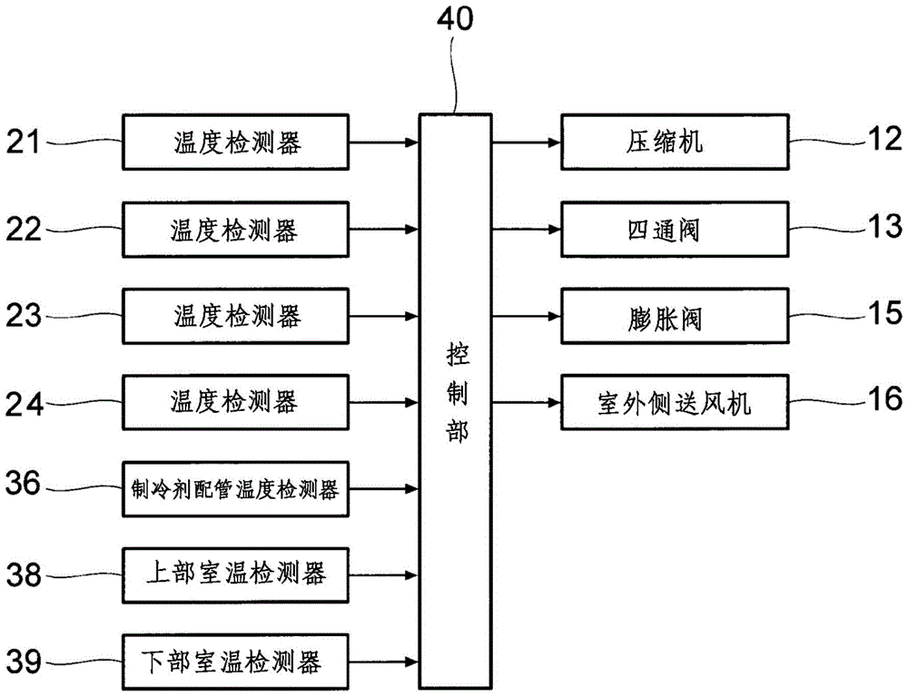
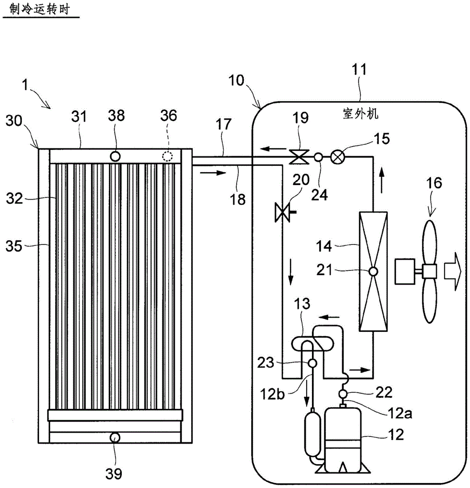
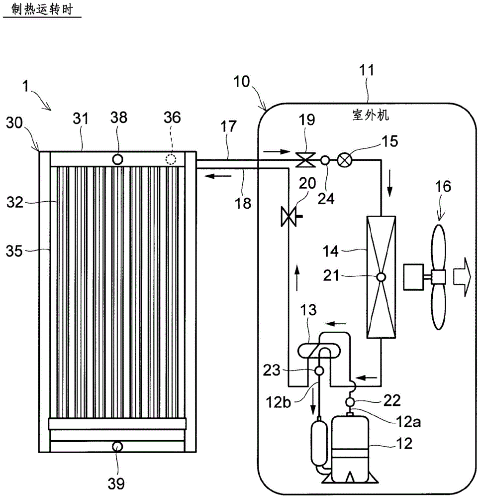
[0047] based on figure 1 A brief structure of the radiant air conditioner 1 will be described. The radiant air conditioner 1 is composed of an outdoor unit 10 and a radiant panel 30 . The radiant panel 30 is arranged indoors, and corresponds to an indoor unit of a common split-type air conditioner.

[0048] The outdoor unit 10 houses a compressor 12, a four-way valve 13, an outdoor heat exchanger 14, an expansion valve 15, and an outdoor blower 16, etc. inside a box body 11, which is made of sheet metal parts and synthetic resin parts. .

[0049] The outdoor unit 10 is connected to the radiation panel 30 through two refrigerant pipes 17 and 18 . The refrigerant piping 17 is used for passing a liquid refrigerant, and is thinner than the refrigerant piping 18 . Therefore, the refrigerant pipe 17 is also called a "liquid pipe", a "thin pipe" and the like. The refrigerant piping 18 is used for passing a gas refrigerant, and is thicker than the refrigerant piping 17 . Therefo...


PUM


Abstract

The invention provides a radiant air conditioner. The radiant air conditioner (1) includes: a radiant panel (30) arranged indoors, an outdoor heat exchanger (14), and refrigerant is passed through refrigerant piping (17, 18) between the radiant panel and the outdoor heat exchanger. A circulating compressor (12) and a control unit (40). The radiation panel is provided with a heat dissipation part (32) inside the box body (31). An upper room temperature detector (38) is arranged on the upper part of the radiation panel, and a lower room temperature detector (39) is arranged on the lower part of the radiation panel. The control unit performs control with reference to an output signal from the upper room temperature detector or the lower room temperature detector.

Description

technical field [0001] The present invention relates to radiant air conditioners. Background technique [0002] In a heat pump air conditioner for residential use, that is, a so-called separate air conditioner in which the outdoor unit and the indoor unit are separated, the usual structure is that the outdoor unit is provided with a heat exchanger and a fan, and the indoor unit is also provided with a heat exchanger. and fan. On the other hand, there is also a separate type air conditioner in which the heat exchanger of the indoor unit is a radiant panel, and the indoor cooling or heating is performed by heat radiation without using a fan. Patent Documents 1 to 3 show examples thereof. [0003] The air conditioner described in Patent Document 1 includes a radiation panel installed on the ceiling of a house. The refrigerant piping is arranged in a serpentine shape inside the radiation panel. During cooling operation, the radiant panels absorb heat for radiant cooling. Du...

Claims


Application Information

Patent Timeline
Patent Type & Authority Patents(China)
IPC IPC(8): F24F11/02F24F1/00F24F5/00
CPCF24F11/83F24F11/30F24F2110/10F24F5/0089F24F11/42F24F11/84F24F11/86F24F2140/00F24F11/871F24F11/89F24F2140/20
Inventor 安藤之仁
Owner SHARP KK
Why Eureka
Try Eureka