

Drainage treatment method
A technology of drainage treatment and process, applied in water/sewage treatment, water/sludge/sewage treatment, chemical instruments and methods, etc., can solve the problem that the treatment method cannot be carefully controlled.
- Summary
- Abstract
- Description
- Claims
- Application Information
AI Technical Summary
Problems solved by technology
Method used
Image

Examples
Embodiment approach 1
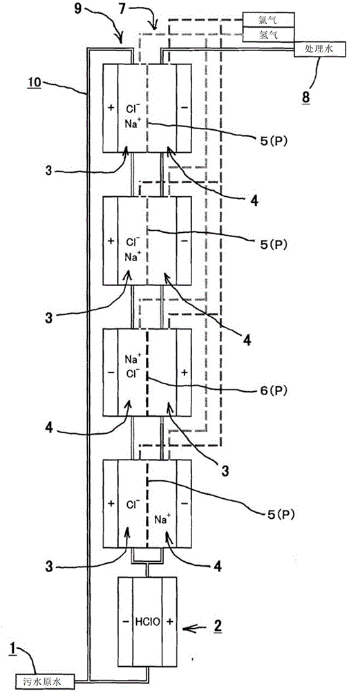
[0048] like figure 1 As shown, in the wastewater treatment method of this embodiment, the wastewater (sewage raw water) 1 is first supplied to the electrolytic cell 2 without a diaphragm. In order to impart conductivity to drainage 1 and supply available chlorine (Cl 2 , HOCl, OCl - ) based on the chloride ion (Cl - ), and NaCl was added to the drainage 1 so that the salt concentration of the drainage 1 was about 3%.
[0049] In addition, electrolysis (2Cl - → Cl 2 +2e - , Cl 2 +H 2 O→HOCl+HCl), and oxidatively decomposes the dirty components (mainly organic components) in the wastewater by the generated hypochlorous acid (HOCl). In addition, the fouling components are directly oxidized by contact with the anode electrode, thereby being decomposed. Furthermore, the pollution components are decomposed by hydroxyl radicals (·OH) generated by electrolysis.
[0050] This wastewater treatment method includes an anode side treatment step through the anode side 3 (electroly...
Embodiment approach 2
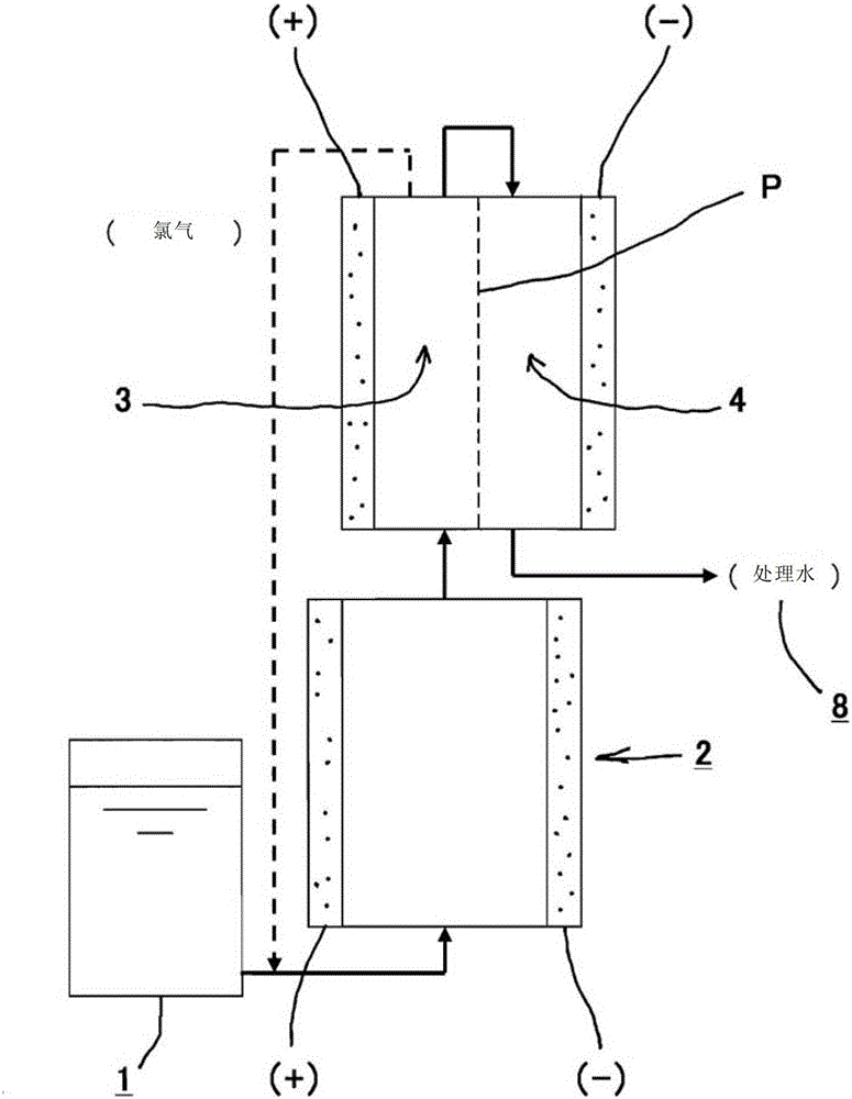
[0065] like figure 2 As shown, in the wastewater treatment method of this embodiment, the wastewater (sewage raw water) 1 is first supplied to the electrolytic cell 2 without a diaphragm. In order to impart conductivity to drainage 1 and supply available chlorine (Cl 2 , HOCl, OCl - ) based on the chloride ion (Cl - ), and NaCl was added to the drainage 1 so that the salt concentration of the drainage 1 was about 3%.
[0066] In addition, electrolysis (2Cl - → Cl 2 +2e - , Cl 2 +H 2 O→HOCl+HCl), and oxidatively decomposes the dirty components (mainly organic components) in the wastewater by the generated hypochlorous acid (HOCl). In addition, the fouling components are directly oxidized by contact with the anode electrode, thereby being decomposed. Furthermore, the pollution components are decomposed by hydroxyl radicals (·OH) generated by electrolysis.
[0067] Next, in the anode side treatment process (electrolysis path on the anode side 3), the concentration of h...
Embodiment approach 3
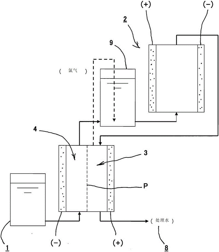
[0072] like image 3 As shown, the wastewater treatment method of this embodiment is to increase the hydrogen ion concentration of the wastewater 1 in the cathode side treatment process (the electrolysis channel of the cathode side 4), so that chlorine gas (refer to Embodiment 2) can be easily dissolved, and it is not necessary to In 1, alkali such as sodium hydroxide (NaOH) is added, but the electrolytic pathway on the cathode side can be used to increase the hydrogen ion concentration pH, thereby making chlorine gas (Cl 2 ) is easy to dissolve, and can reduce the amount of alkali added, thereby reducing or even reducing the cost of the medicament.
[0073] That is, the pH tends to increase (2H 2 O+2e - →H 2 +2OH - ), while chlorine gas (Cl 2 ) is easily soluble (Cl 2 +2OH - → 2HOCl), and in the chlorine gas dissolving tank 9, the remaining available chlorine in the anode side treatment process (the electrolysis path of the anode side 3) described later can be foamed a...
PUM
 Abstract
Description
Claims
Application Information