Outward-turning rotating liquid changer

An external rotation, liquid container technology, applied in the direction of the device introduced into the body, can solve the problems of large material consumption, large pipeline volume, blood backflow, etc., and achieve the effect of reducing labor intensity, safe infusion care, and saving time.

Inactive Publication Date: 2015-04-29
李志文
View PDF9 Cites 2 Cited by
  • Summary
  • Abstract
  • Description
  • Claims
  • Application Information

AI Technical Summary

Problems solved by technology

[0004] In the prior art, when the above process is carried out, the infusion tube is manually pulled out from the previous vial and inserted into the next vial by the medical staff. Generally, the medical staff will monitor each patient. When the medical staff When noticing that the injection solution in a certain bottle is about to run out, he will go to the patient some time in advance to prepare for a dressing change; when the medical staff is too busy to notice, the patient himself will call the medical staff to change the dressing; In some cases, neither the medical staff nor the patients notice that the injection solution in the hanging bottle has been used up or is about to be used up. At this time, the infusion tube is still inserted on the patient. The blood pressure in the human body will cause the blood to flow back into the infusion tube. This situation is very dangerous. If it is not handled properly in time, it will lead to very serious consequences
[0005] Although the above situation is relatively rare, once it happens, the consequences will be serious. Therefore, the liquid changing method and liquid changing equipment in the prior art are less effective and have greater risks.
[0006] Chinese patent CN201320310008.9 discloses an infusion set, which simply connects multiple infusion tubes through a three-way connection, which consumes a lot of materials, has a large pipeline volume, poor practicability, and cannot realize automatic control; Chinese patent CN 201320073717.X discloses a new type of infusion set, which has a relatively simple structure and a large volume, and also cannot realize automatic control

Method used


Image

  • Outward-turning rotating liquid changer
  • Outward-turning rotating liquid changer
  • Outward-turning rotating liquid changer

Examples


Embodiment

[0041] Examples, see Figure 1-8

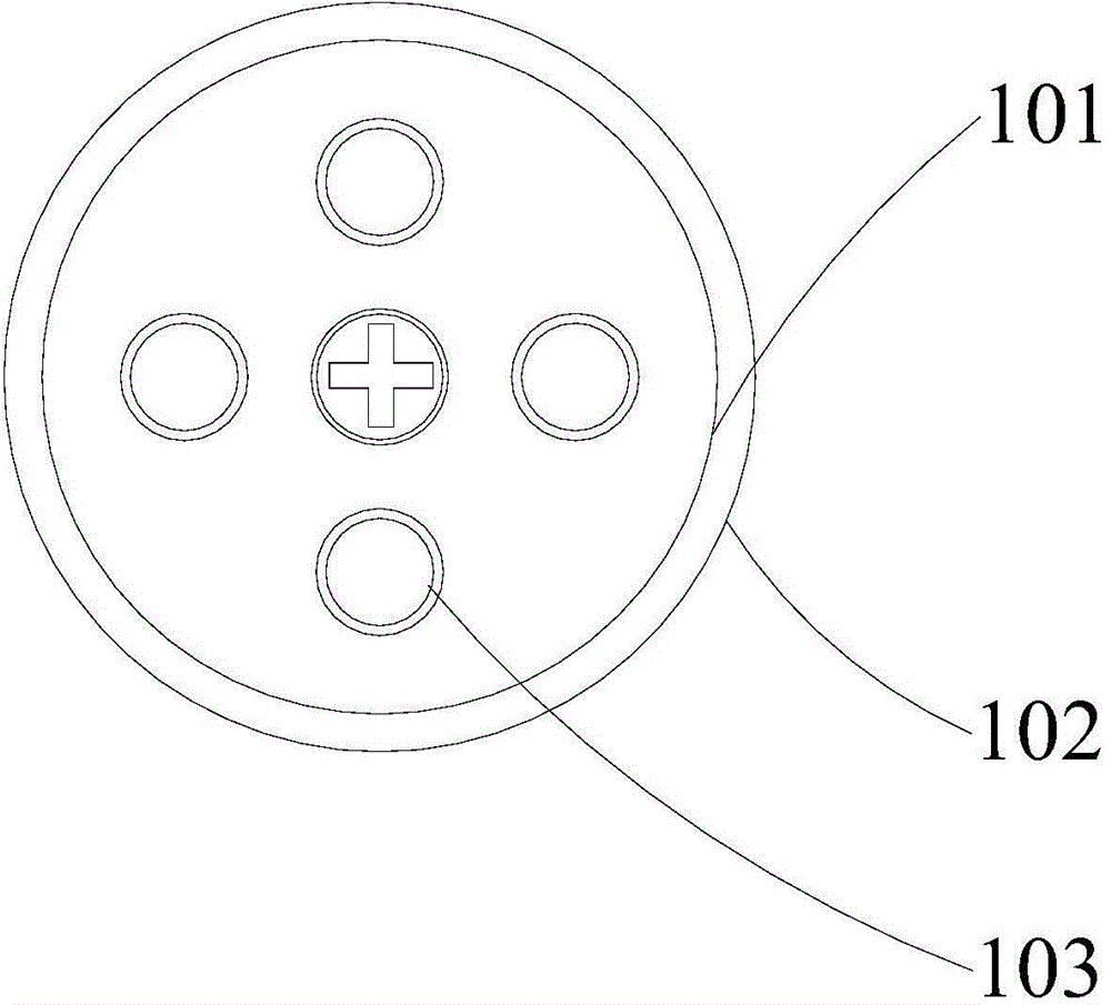
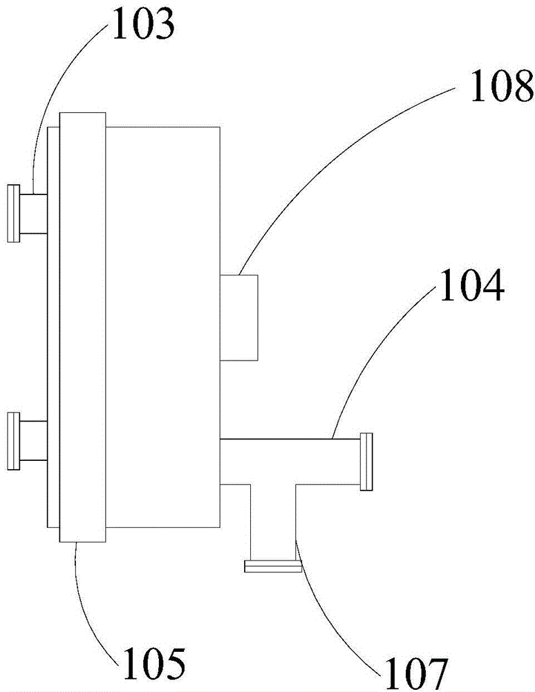
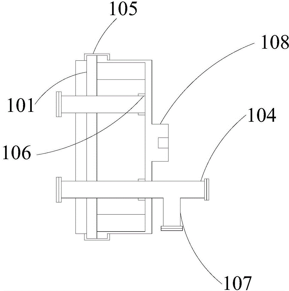
[0042] The externally rotating rotary liquid changer provided in this embodiment includes an inner shaft 101 and a housing 102 sleeved outside the inner shaft 101. The housing 102 can rotate relative to the inner shaft 101. The inner shaft 101 is provided with a plurality of The first infusion tube joint 103 communicated with the outside, and a second infusion tube joint 104 communicated with the outside is provided on the shell 102, and the second infusion tube joint 104 can be connected with each first infusion tube respectively by rotating the shell 102 The joints 103 communicate with each other, and both the first infusion tube joint 103 and the second infusion tube joint 104 can be connected with the infusion tube.

[0043] The infusion tube includes an upper infusion tube 206 connected with the hanging bottle 203 and a lower infusion tube 207 connected with the scalp needle.

[0044] When this externally rotating rotary liquid changer...


PUM


Abstract

The invention provides an outward-turning rotating liquid changer and belongs to the field of medical instrument. The outward-turning rotating liquid changer comprises an internal shaft and a shell sleeving on the exterior of the internal shaft, the shell can rotate relative to the internal shaft, a plurality of first infusion tube joints communicated with the exterior are arranged in the interior of the internal shaft, a second infusion tube joint communicated with the exterior is arranged on the shell, the shell is rotated to enable the second infusion tube joint to be communicated with the first infusion tube joints respectively, and both the first infusion tube joints and the second infusion tube joint can be connected with an infusion tube. By the arrangement, automatic switching of infusion bottles can be realized during patient infusion, simpleness and rapidness are achieved, the risk of bottle changing is lowered, labor intensity of medical workers is reduced, and infusion processes are effectively monitored.

Description

technical field [0001] The invention relates to the field of medical equipment, in particular to an externally rotating rotary liquid changer. Background technique [0002] Infusion is a treatment process that almost everyone has experienced. Infusion is also known as drip or hanging water. It is a large dose (more than 100ml for one administration) injection that is infused into the body by intravenous infusion. Injections are usually packaged in glass or plastic vials or bags without preservatives or bacteriostats. When in use, the drip rate is adjusted through the infusion device, and it enters the vein continuously and steadily to replenish body fluids, electrolytes or provide nutrients or other substances. [0003] In severe cases, the general doctor will prescribe multiple bottles (or bags) of injections to the patient, and the patient will inject the injections into the vein one by one during the infusion, and the previous bottle of injection needs to be replaced af...

Claims


Application Information

Patent Timeline
Patent Type & Authority Applications(China)
IPC IPC(8): A61M5/14
CPCA61M5/1408
Inventor 李志文
Owner 李志文
Why Eureka
Try Eureka