
An automatic processing production line and processing method for side holes of ladder-type bridge frames

An automatic processing and production line technology, applied in the direction of perforation tools, metal processing equipment, manufacturing tools, etc., can solve the problems of affecting the speed of cold forming, complicated mold replacement process, low processing and production efficiency, etc., to ensure accuracy and reliability. performance, reduction of processing steps, and easy management

Active Publication Date: 2016-08-24
SHANDONG JINBOLIDA PRECISION MASCH CO LTD
View PDF5 Cites 0 Cited by
  • Summary
  • Abstract
  • Description
  • Claims
  • Application Information

AI Technical Summary

Problems solved by technology

Processing according to the above process has the following defects: (1) a large number of supporting molds need to be made to be suitable for products of different specifications, and a large number of molds are not easy to manage; (2) the process of re-changing molds is complicated; (3) the process is cumbersome and labor-intensive (4) low processing efficiency; (5) high manufacturing cost
[0003] In modern technology, the production process of punching first and then forming is often used. For such a production line, the speed of subsequent cold bending is seriously affected by punching, and equipment fraud is expensive.

Method used


Image

  • An automatic processing production line and processing method for side holes of ladder-type bridge frames
  • An automatic processing production line and processing method for side holes of ladder-type bridge frames
  • An automatic processing production line and processing method for side holes of ladder-type bridge frames

Examples


Embodiment Construction

[0040] The present invention will be described in further detail below in conjunction with the accompanying drawings.

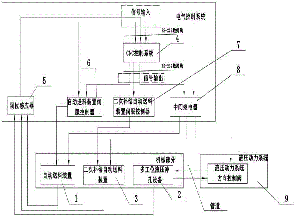
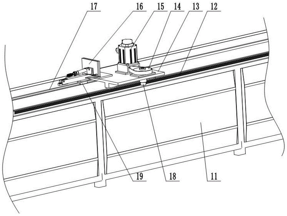
[0041] like figure 1 , shown in 2, a kind of ladder type bridge side hole automatic processing production line is mainly made up of electric control system, hydraulic power system, mechanical part; Described electric control system is electrically connected with mechanical part, hydraulic power system respectively, and described hydraulic pressure The power system is connected to the mechanical part by pipes; the mechanical part includes an automatic feeding device 1, a multi-station hydraulic punching device 2, and a secondary compensation automatic feeding device 3. The automatic feeding device 1 is located at the beginning of the production line and the multi-station hydraulic The punching equipment 2 is docked, and the end of the three-position production line of the secondary compensation feeding device is docked with the multi-station hydraulic punching...


PUM


Abstract

The invention discloses an automatic cable ladder knee hole machining production line and a machining method, and particularly relates to an automatic cable ladder knee hole machining production line which is used for automatically machining various knee holes in ladder strings and applicable to different specifications of ladder strings. The automatic cable ladder knee hole machining production line mainly comprises an electrical control system, a hydraulic power system and a mechanical portion, the electrical control system is respectively electrically connected with the mechanical portion and the hydraulic power system, the hydraulic power system is connected with the mechanical portion through a pipeline, the mechanical portion comprises an automatic feeding device, a multi-station hydraulic punching device and a secondary compensation automatic feeding device, the automatic feeding device is positioned at an initial end of the production line and in butt joint with the multi-station hydraulic punching device, and the secondary compensation automatic feeding device is positioned at the tail end of the production line and in butt joint with the multi-station hydraulic punching device. The automatic cable ladder knee hole machining production line is high in universality, high in machining efficiency and low in manufacturing cost, and a die is simply adjusted.

Description

technical field [0001] The present invention relates to the manufacture field of ladder-type bridges used for wire routing of electric control systems in the manufacture of electromechanical equipment, in particular to an automatic ladder-type bridge-side hole that automatically processes various side holes on the side of the ladder and can be applied to sides of different specifications. Processing line. Background technique [0002] There are generally three hole types for the side holes of the ladder bridge, the waist-shaped hole for docking with other bridges, that is, the long guide hole, the round hole for installing the grounding wire, and the square hole for installing the bridge cover. The processing of the bridge side hole is generally processed by a mechanical punching machine. During processing, it is necessary to make a positioning backer as a processing reference, and then manually position the workpiece, and at the same time operate the foot switch of the mech...

Claims


Application Information

Patent Timeline
Patent Type & Authority Patents(China)
IPC IPC(8): B21D28/24B21D28/34B21D43/02B21D43/00
CPCB30B15/04B30B15/30
Inventor 李广君
Owner SHANDONG JINBOLIDA PRECISION MASCH CO LTD
Learn More