Hole aligning punching machine for pipe

A punching machine and pipe technology, applied in metal processing equipment, feeding devices, manufacturing tools, etc., can solve the problems of low punching efficiency, single die base structure, and pipe position deviation, so as to reduce labor intensity and improve Production quality, good punching effect

Inactive Publication Date: 2015-04-29
JIANGSU YAFENG TECH GRP CO LTD
View PDF9 Cites 4 Cited by
  • Summary
  • Abstract
  • Description
  • Claims
  • Application Information

AI Technical Summary

Problems solved by technology

Originally, when punching a number of circular inner sockets on the pipe of the inner jacking tube, the pipe is usually manually pushed to move on the mold base, and then the pipe is punched by a punching machine, the punching efficiency is low, The labor intensity of the workers is high, and the structure of the mold base is relatively simple. During the punching process, the pipe is prone to position deviation, resulting in misalignment of some circular inner sockets and scrapping

Method used


Image

  • Hole aligning punching machine for pipe

Examples


Embodiment Construction

[0009] The specific content of the present invention will be described in detail below in conjunction with the accompanying drawings and specific embodiments.

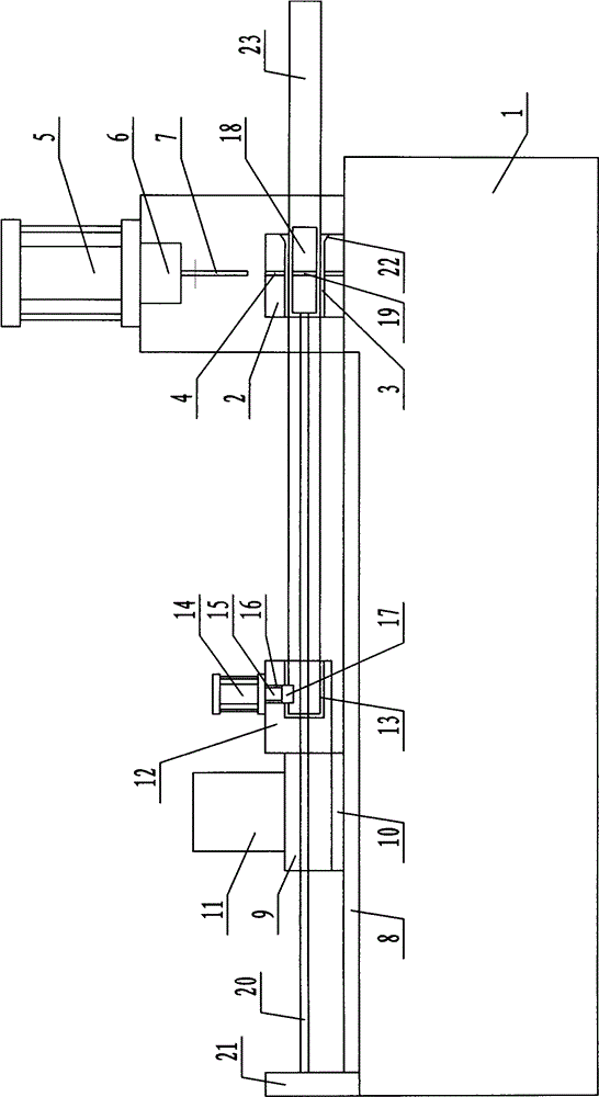
[0010] Such as figure 1 As shown, the pipe pair hole punching machine includes: a frame 1, a mold base 2 fixedly arranged at the front end of the frame 1, a horizontal feed channel 3 arranged in the mold base 2 and a first vertical punch guide hole 4 , a punching cylinder 5 is arranged on the frame 1 at the upper end of the mold base 2, the piston rod 6 of the punching cylinder 5 is connected with a punch 7, and the punch 7 is guided with the first vertical punch The holes 4 cooperate with each other, and the frame 1 at the rear end of the mold base 2 is provided with a slide rail 8, and the slide table 9 is slidably arranged on the slide rail 8 through the slide block 10, and the slide table 9 is provided with a 10 is electrically connected to the servo drive motor 11, a pipe pushing block 12 is connected to one side...


PUM


Abstract

The invention discloses a hole aligning punching machine for a pipe. The machine comprises a rack, a die seat which is fixedly arranged at the front end of the rack, a transverse feeding channel and a first vertical punch guide hole, wherein the transverse feeding channel and the first vertical punch guide hole are formed in the die seat; a punching cylinder is arranged on the rack at the upper end of the die seat; a piston rod of the punching cylinder is connected with the punch; the punch is matched with the first vertical punch guide hole; a slide rail is arranged on the rack at the rear end of the die seat; a sliding table is glidingly arranged on the slide rail through a sliding block; a servo driving motor which is electrically connected with the sliding block is arranged on the sliding table; a pipe pushing block is connected to one side of the sliding table; a pipe end positioning hole is formed in one side of the pipe pushing block; a compressing cylinder is arranged at the upper end of the pipe pushing block.

Description

technical field [0001] The invention relates to a punching device, in particular to a pipe punching machine with good punching effect. Background technique [0002] In the field of construction, the aluminum alloy building formwork system is widely used because of its advantages such as high degree of standardization, light weight, strong bearing capacity, high matching precision, recyclable use, and smooth surface after concrete pouring. In the related art, when building an aluminum alloy building formwork system, in order to meet the installation of aluminum formworks with different storey heights, it is necessary to use formwork single roof support devices with different heights. The structure of the existing formwork single roof support device mainly includes: an inner jack tube and an outer jack tube sheathed outside the inner jack tube, and the inner jack tube has A number of circular inner sockets arranged equidistantly in the length direction, a wire tube is welded ...

Claims


Application Information

Patent Timeline
Patent Type & Authority Applications(China)
IPC IPC(8): B21D28/28B21D43/00B21D43/02
CPCB21D28/28B21D43/006
Inventor 郭友峰
Owner JIANGSU YAFENG TECH GRP CO LTD
Why Eureka
Try Eureka