
metal forming equipment

A metal forming and equipment technology, applied in the field of metal forming equipment, can solve the problems of increased volume of vacuum chamber, decreased equipment stability, increased sealing positions, etc., to achieve the reduction of space volume, ensure mass production, ensure airtightness and guarantee pressure effect

Active Publication Date: 2017-02-15
BYD CO LTD
View PDF10 Cites 0 Cited by
  • Summary
  • Abstract
  • Description
  • Claims
  • Application Information

AI Technical Summary

Problems solved by technology

[0002] In order to reduce the generation of air bubbles in the metal forming process, there is a method of vacuuming the mold in the related art, but due to the unique working mode, the vacuum degree in the mold can only reach about 80%, and the melting and injection positions cannot achieve a vacuum environment, and Does not have the function of completely overcoming air bubbles and preventing oxidation
[0003] In the related art, there is also a method of protecting the injection position and the smelting position with a vacuum chamber, but this method has the following defects: first, such a method will increase the volume of the vacuum chamber and significantly increase the number of sealing positions. The stability of the device itself is reduced, and it is difficult to realize batch application in the true sense
However, for amorphous alloys with high vacuum requirements, it will be difficult to achieve short-term vacuum operation and pressure holding in a large-volume vacuum chamber, which will bring major scientific research problems to the mass production of amorphous alloy forming
At the same time, this also increases the difficulty of the design of the external interface for the actions required for molding, and increases the instability of the equipment.

Method used


Image

  • metal forming equipment
  • metal forming equipment
  • metal forming equipment

Examples


Embodiment Construction

[0020] Embodiments of the present invention are described in detail below, examples of which are shown in the drawings, wherein the same or similar reference numerals designate the same or similar elements or elements having the same or similar functions throughout. The embodiments described below by referring to the figures are exemplary only for explaining the present invention and should not be construed as limiting the present invention.

[0021] In describing the present invention, it should be understood that the terms "center", "longitudinal", "transverse", "upper", "lower", "front", "rear", "left", "right", " The orientations or positional relationships indicated by "vertical", "horizontal", "top", "bottom", "inner" and "outer" are based on the orientations or positional relationships shown in the drawings, and are only for the convenience of describing the present invention and Simplified descriptions, rather than indicating or implying that the device or element refe...


PUM


Abstract

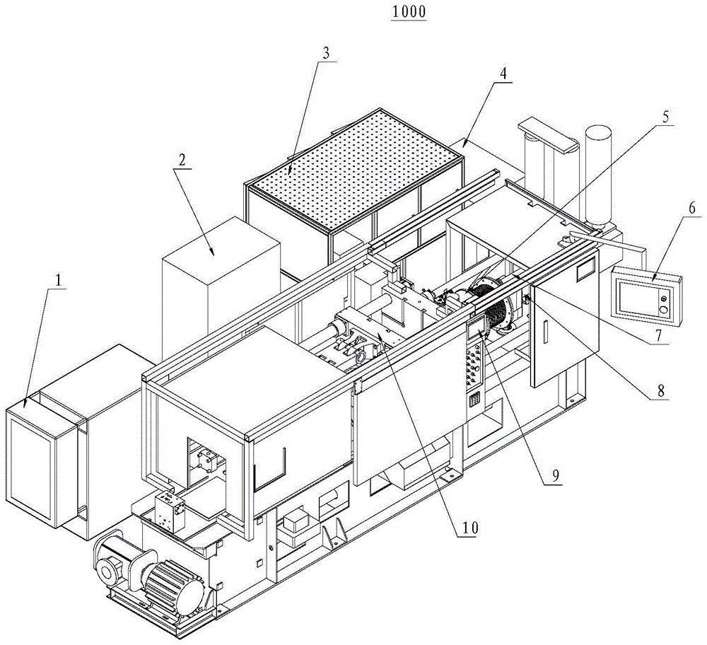
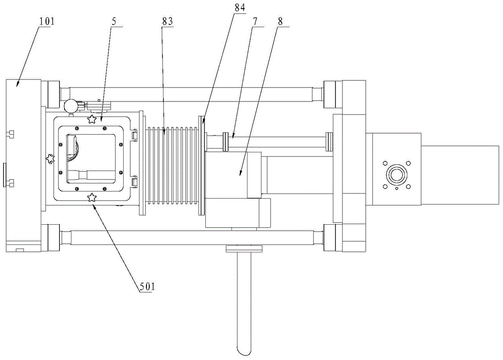
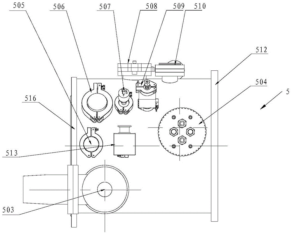
The invention discloses metal forming equipment. The metal forming equipment comprises a melting device, a die device, a press-injection device and a vacuuming device. A crucible is arranged in the melting device, the die device is connected with a melting chamber hermetically, a barrel component of the press-injection device is arranged at the joint of the die device and the melting device, a part of the barrel component extends into the melting chamber and is arranged below the crucible, and a press-injection unit presses and injects raw materials into the die device and is hermetically connected with the melting device. The vacuuming device is connected with the melting chamber and the die device. According to the metal forming equipment, the to-be-vacuumed spaces of the press-injection device and the melting device are combined, so that space to be vacuumed is greatly reduced, and sealing and pressure maintaining of the vacuum space are ensured beneficially. In addition, the vacuuming device can quickly vacuum to meet the requirement of vacuum degree of easily oxidized metal melting within a short time, and batch production of easily-oxidized metal forming is ensured.

Description

technical field [0001] The invention relates to the field of metal smelting, in particular to a metal forming equipment. Background technique [0002] In order to reduce the generation of air bubbles in the metal forming process, there is a method of vacuuming the mold in the related art, but due to the unique working mode, the vacuum degree in the mold can only reach about 80%, and the melting and injection positions cannot achieve a vacuum environment, and It does not have the function of completely overcoming air bubbles and preventing oxidation. [0003] In the related art, there is also a method of protecting the injection position and the smelting position with a vacuum chamber, but this method has the following defects: first, such a method will increase the volume of the vacuum chamber and significantly increase the number of sealing positions. The stability of the device itself is reduced, and it is difficult to realize batch applications in the true sense. Second...

Claims


Application Information

Patent Timeline
Patent Type & Authority Patents(China)
IPC IPC(8): B22D17/04B22D17/14
CPCB22D17/20B22D17/2015
Inventor 宫清赵树明王亚楠陈秋绘王晓华唐柳平
Owner BYD CO LTD
Learn More