
Spindle component of oblique machining tool

A technology for processing machine tools and spindles, applied to metal processing machinery parts, metal processing equipment, manufacturing tools, etc., can solve the problems of easy deformation of the spindle, unstable processing, inconvenient observation, etc., and achieve long service life, non-deformation, and balanced performance Good results

Inactive Publication Date: 2015-04-29
CHENGDU ZHONGYUANXIN ELECTRONICS TECH
View PDF0 Cites 0 Cited by
  • Summary
  • Abstract
  • Description
  • Claims
  • Application Information

AI Technical Summary

Problems solved by technology

[0005] The technical problem to be solved by the present invention is: the existing processing is usually carried out on a vertical plane, which is not convenient for observation, and the oblique main shaft is easily deformed, resulting in unstable processing

Method used


Image

  • Spindle component of oblique machining tool
  • Spindle component of oblique machining tool

Examples


Embodiment Construction

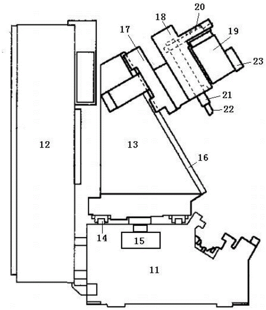
[0020] see figure 1 , The oblique processing machine tool includes a base body 11, a control box 12 is provided on the rear side of the base body 11, and an electrical system and a hydraulic system are provided in the control box 12.

[0021] A processing table 13 is arranged on the upper surface of the base body 11, the upper surface of the base body 11 is provided with two slide rails 14, and the bottom surface of the processing table 13 has a chute corresponding to the slide rails, so that the processing table 13 can slide on the upper surface of the base 11. In order to drive the sliding of the processing table 13, the base 11 is provided with a driving motor 15, and the driving motor 15 drives the sliding of the processing table 13 through a transmission device.

[0022] One side of the base body 11 is provided with an oblique clamping device to clamp the workpiece obliquely.

[0023] Optionally, the transmission device includes a transmission gear driven by the output s...


PUM


Abstract

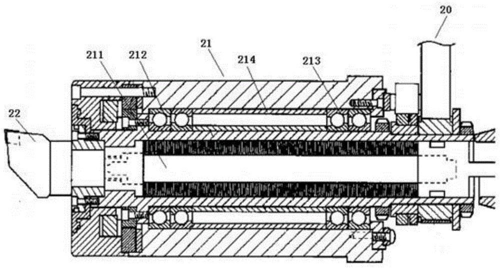
The invention discloses a spindle component of an oblique machining tool. One end of a transmission spindle is connected to a chain of a chain transmission device and is driven by a cutting motor, wherein the other end of the transmission spindle stretches out of a body and is fixedly connected to a cutting head; a first bearing component and a second bearing component are respectively arranged on two sides of the middle part of the transmission spindle; an elastic abutting and pushing part is arranged between the first bearing component and the second bearing component. By virtue of the oblique design, operators can conveniently observe; the machining processes and targets can be conveniently and accurately controlled in real time; the spindle component is high in balancing performance, high in strength, not liable to deform and relatively long in service life.

Description

technical field [0001] The invention relates to a main shaft assembly of an oblique machining machine tool. Background technique [0002] During the drilling process, due to the need for timely observation during drilling, usually in the preliminary processing, the operator needs to temporarily stop the drill bit for observation when processing a certain depth, and in order to observe better, the operator needs to use the eyes Only when it is placed directly above the drilling hole can accurate observation be carried out. However, since the existing machine tools are usually placed flat, it is easy to cause the observation angle to be difficult to accurately vertically directly above the entire drilling hole. [0003] The oblique setting has better requirements for the balance of the main shaft, and puts forward the need for more stability. [0004] For this reason, in view of the above-mentioned defects, the designer of the present invention researches and designs a spindl...

Claims


Application Information

Patent Timeline
Patent Type & Authority Applications(China)
IPC IPC(8): B23B39/00B23B19/02
CPCB23Q1/70B23Q1/25B23Q5/10
Inventor 龙宁
Owner CHENGDU ZHONGYUANXIN ELECTRONICS TECH
Learn More