Eureka AIR delivers breakthrough ideas for toughest innovation challenges, trusted by R&D personnel around the world.

Numerical-control lathe tool table with convenience in assembling and disassembling tools

A technology of CNC lathe and tool table, which is applied in the direction of manufacturing tools, positioning devices, metal processing machinery parts, etc., and can solve the problem of single structure of CNC lathe tool table

Inactive Publication Date: 2015-04-29
滁州用朴合金工具有限公司
View PDF8 Cites 2 Cited by
  • Summary
  • Abstract
  • Description
  • Claims
  • Application Information

AI Technical Summary

Problems solved by technology

However, the structure of the CNC lathe tool table is single, and the tools are located in the same plane. It is not suitable for the production and processing of small and complex workpieces, and cannot cope with different situations.

Method used


Image

  • Numerical-control lathe tool table with convenience in assembling and disassembling tools
  • Numerical-control lathe tool table with convenience in assembling and disassembling tools

Examples


Embodiment Construction

[0020] The present invention will be specifically introduced below in conjunction with the accompanying drawings and specific embodiments.

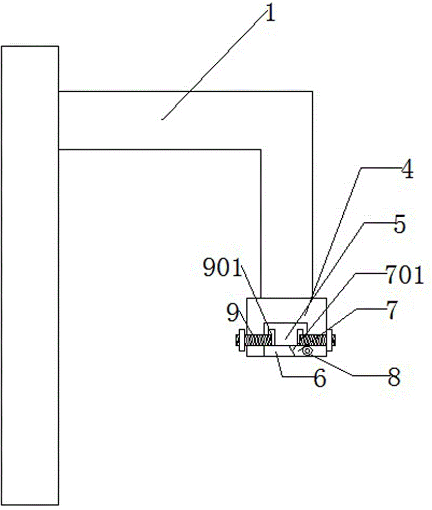
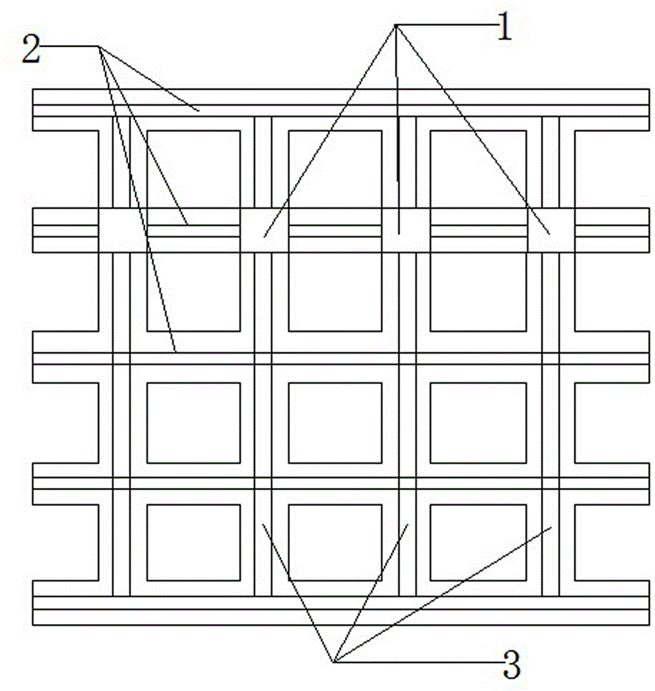
[0021] The CNC lathe tool table for convenient loading and unloading of tools includes: a moving component wall, a tool rack 1 that is movable at one end of the moving component wall, and an installation component fixed at the other end of the tool rack 1 and used for installing tools; the moving component wall includes: lateral moving parts, The vertical moving part intersecting with the lateral moving part, the mounting assembly includes: the mounting block 4 connected to the tool holder 1, the receiving groove 5 arranged on the mounting block 4 and used to accommodate the tool hook, the limit plate 6 of the limit hook, The movable plate 7 is clamped on the limiting plate 6 and closes the above-mentioned receiving groove 5, and stabilizes the position of the tool hook and runs through the limiting screw 9 of the mounting block 4; a hinge...


PUM


Abstract

The invention discloses a numerical-control lathe tool table with convenience in assembling and disassembling tools. The numerical-control lathe tool table comprises moving assembly walls, tool frames and mounting assemblies. One end of each tool frame can move on the corresponding moving assembly wall, and each mounting assembly is fixed to the other end of the corresponding tool frame and is used for mounting the corresponding tools; the moving assembly walls comprise transverse moving components and vertical moving components, the vertical moving components cross the transverse moving components, each mounting assembly comprises a mounting block, an accommodating groove, a limiting plate, a movable plate and limiting screws, the mounting blocks are connected to the tool frames, the accommodating grooves are formed in the mounting blocks and are used for accommodating tool hooks, the hooks can be limited by the limiting plates, the movable plates are movably clamped on the limiting plates, the accommodating grooves can be closed by the movable plates, the tool hooks can be stabilized by the limiting screws, and the limiting screws penetrate the mounting blocks. The numerical-control lathe tool table has the advantages that the multiple types of tools can be simultaneously used for machining and can be voluntarily repositioned according to the types of components or machining requirements, and accordingly the numerical-control lathe tool table is wide in application range and high in operation efficiency; the numerical-control lathe tool table is provided with the mounting assemblies, can bring convenience for assembling and disassembling the tools and accordingly is adaptive to large quantities of conditions and requirements; the numerical-control lathe tool table is provided with the limiting screws, accordingly, the position stability of the tools can be guaranteed, and the tools can be prevented from shaking left and right due to instability.

Description

technical field [0001] A tool table, in particular a CNC lathe tool table. Background technique [0002] CNC lathe is a computer numerical control lathe. CNC machine tool is a mechatronic product integrating machinery, electricity, hydraulic pressure, pneumatic, microelectronics and information. It is a high-precision, high-efficiency, high-automated and high flexibility and other advantages of the machine tool. It has played a good economic effect in the mass production of complex parts. However, the CNC lathe tool table has a single structure and the tools are located in the same plane, which is not suitable for the production and processing of small and complex workpieces, and cannot respond to different situations requiring strains. The prior art has not yet solved such problems. Contents of the invention [0003] In order to solve the deficiencies of the prior art, the object of the present invention is to provide a tool that can be processed simultaneously with mul...

Claims


Application Information

Patent Timeline
IPC IPC(8): B23Q1/25B23Q3/00
CPCB23Q1/25B23Q3/00
Inventor 祁长岭
Owner 滁州用朴合金工具有限公司
Why Eureka
Eureka Blog
Learn More