Pipe cutting device

A cutting device and pipe technology, applied in stone processing tools, stone processing equipment, work accessories, etc., can solve the problems of difficult cutting and smooth cross-section incision, affecting the splicing quality of ceramic pouring pipes, ceramic pouring pipes are fragile, etc.

Active Publication Date: 2015-04-29
浙江杭机铸造有限公司
View PDF9 Cites 13 Cited by
  • Summary
  • Abstract
  • Description
  • Claims
  • Application Information

AI Technical Summary

Problems solved by technology

Because there is no special cutting tooling device, the ceramic pouring tube is fragile during the cutting process, and the cross-section is difficult to cut flat, which not only affects the splicing quality of the ceramic pouring tube, but also increases the consumption of the ceramic tube due to cutting damage

Method used


Image

  • Pipe cutting device
  • Pipe cutting device
  • Pipe cutting device

Examples


Embodiment Construction

[0022] The technical solutions of the embodiments of the present invention will be explained and described below in conjunction with the drawings of the embodiments of the present invention, but the following embodiments are only preferred embodiments of the present invention, not all of them. Based on the examples in the implementation manners, other examples obtained by those skilled in the art without making creative efforts all belong to the protection scope of the present invention.

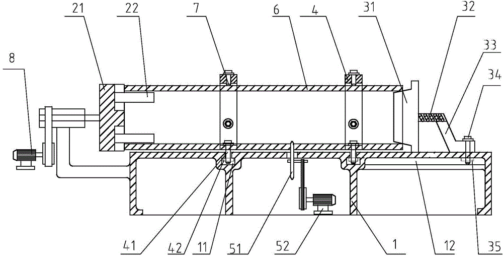
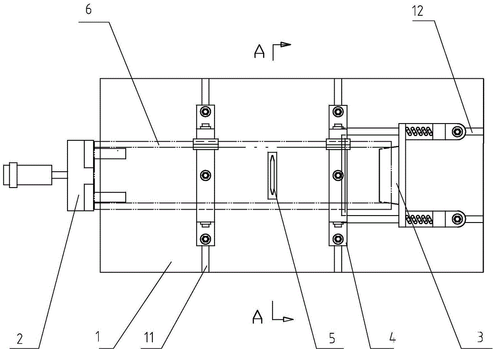
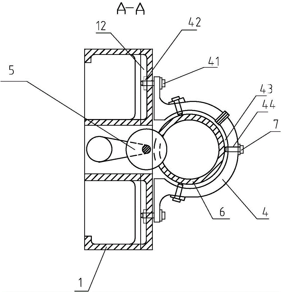
[0023] refer to figure 1 , figure 2 and image 3 , a pipe cutting device shown includes a base 1, a cutting tool 5 and a clamp assembly, the base 1 is provided with a clamp assembly, and after the clamp assembly clamps the pipe 6, the cutting tool 5 cuts the pipe 6. The clamp assembly includes a left collet 2, a right collet 3 and a collet driving unit 8, the pipe is clamped between the left collet 2 and the right collet 3, and the collet driving unit 8 drives the left collet 2 or the rig...


PUM


Abstract

The invention discloses a pipe cutting device, belongs to the field of casting, and solves the technical problem that in the prior art, the ceramic cast pipe is easy to break. The pipe cutting device provided by the invention includes a pedestal, a cutting tool and a fixture assembly, wherein the fixture assembly includes a left chuck, a right chuck and a chuck driving unit; a pipe is clamped between the left and right chucks; the chuck driving unit drives the left or right chuck to further drive the pipe to rotate around the axis of the pipe; the cutting tool cuts along the rotating direction of the pipe; the pipe cutting device also includes a pipe support fixedly connected onto the pedestal, wherein the pipe support is arranged on the outer wall of the pipe in an embracing manner, and a positioning piece for clamping the pipe in the radial direction is arranged on the pipe support. The pipe cutting device is applied to cutting the pipes, particularly cutting the ceramic pipes.

Description

【Technical field】 [0001] The invention relates to a pipe material cutting device, in particular to a cutting device for cutting ceramic pipes. 【Background technique】 [0002] In the production process of large-scale casting molding, it is necessary to pre-place ceramic tubes in the sand mold as runners, and the ceramic pouring tubes play the role of guiding the molten metal. Due to the different sizes of the sand molds, the length and diameter of the ceramic pouring pipes used are different. Usually, the operator must cut and intercept the ceramic pipes according to the required pipe diameter specifications and length dimensions, and then splice them for use. Because there is no special cutting tooling device, the ceramic pouring tube is fragile during the cutting process, and the cross-section incision is difficult to cut flat, which not only affects the splicing quality of the ceramic pouring tube, but also increases the consumption of the ceramic tube due to cutting damag...

Claims


Application Information

Patent Timeline
Patent Type & Authority Applications(China)
IPC IPC(8): B28D1/24B28D7/04
CPCB28D1/24B28D7/04
Inventor 桑迪方毅樊智勇陈建国王海君钱铁民韩国松
Owner 浙江杭机铸造有限公司
Why Eureka
Try Eureka