
Oil cup type pad printing machine

A pad printing machine and ink cup technology, applied in printing machines, rotary printing machines, printing, etc., can solve the problems of high complexity of printing heads, long pad printing work time, low work efficiency, etc., and achieve pad printing work rhythm Compact, time-saving and efficient work

Inactive Publication Date: 2015-04-29
长兴艾飞特科技股份有限公司
View PDF8 Cites 28 Cited by
  • Summary
  • Abstract
  • Description
  • Claims
  • Application Information

AI Technical Summary

Problems solved by technology

[0004] In order to solve the problems of high complexity of printing head control, long working time of the whole pad printing and low work efficiency of the existing oil cup type pad printing machine, the present invention provides a simple structure, compact pad printing work rhythm, saving time and An oil cup type pad printing machine that is easy to control

Method used


Image

  • Oil cup type pad printing machine

Examples


Embodiment Construction

[0012] The present invention will be further described below in conjunction with the accompanying drawings and specific embodiments.

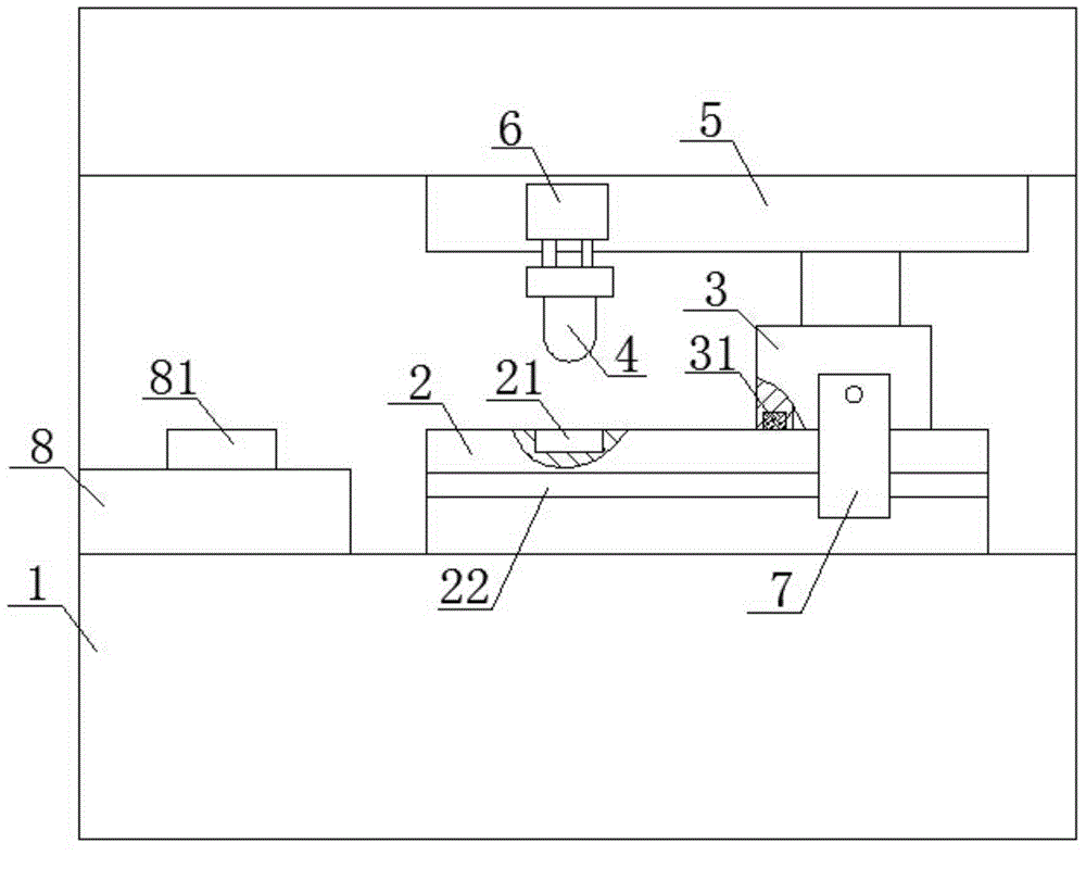
[0013] Such as figure 1 As shown, an oil cup type pad printing machine includes a frame 1, a pad printing steel plate 2 with a concave pattern 21, an oil cup 3, and a pad printing rubber head 4. It is characterized in that the frame 1 is provided with a horizontal The slider 5 slides in the same direction, the upper end of the oil cup 3 is connected to the slider 5, and the lower end of the oil cup 3 is pressed on the upper surface of the pad printing plate 2. The side of the pad printing plate 2 is provided with a guide groove 22, and the guide groove 22 fits There is a guide block 7 that can slide along the guide groove, the upper end of the guide block 7 extends upwards and is connected to the side of the oil cup 3; the slider 5 is provided with a cylinder 6, which is a double-piston cylinder, and the pad printing rubber head 4 is connected ...


PUM


Abstract

The invention provides an oil cup type pad printing machine which is aimed at solving the problems of the existing oil cup type pad printing machines that the complicity of control is high, and the whole pad printing work is long in time and low in work efficiency. The oil cup type pad printing machine comprises a machine frame, a pad printing steel plate with a sunk pattern, an oil cup and a pad printing glue head, wherein a sliding block which can slide along the horizontal direction is arranged on the machine frame, the upper end of the oil cup is connected onto the sliding block, the lower end of the oil cup is press-fit on the upper surface of the pad printing steel plate, a guiding groove is formed in the side face of the pad printing steel plate, a guiding block which can slide along the guiding groove is matched with the guiding groove, and the upper end of the guiding block extends upwards and is connected onto the side face of the oil cup; an air cylinder is arranged on the sliding block, the pad printing glue head is connected to the lower end of the air cylinder, and the horizontal distance between the pad printing glue head and the oil cup is equal to the distance between a position, for fixing a printed workpiece, on a printed workpiece fixing table and the sunk pattern. The oil cup type pad printing machine has the beneficial effects that the structure is simple, the rhythm of pad printing work is compact, time is saved, control is facilitated, and the work efficiency is high.

Description

technical field [0001] The invention relates to the field of printing equipment, in particular to an oil cup type pad printing machine. Background technique [0002] The working principle of the oil cup pad printing machine is: the oil cup filled with ink moves back and forth in a straight line on the surface of the pad printing steel plate, and the ink in the oil cup fills in the concave pattern on the surface of the pad printing steel plate during the movement; The pad printing rubber head moves vertically downwards to pick up the ink filled in the concave pattern, then translates to the top of the printing workpiece, and then moves downwards to emboss the ink that sticks to the surface of the pad printing rubber head to form the concave pattern On the surface of the printing workpiece. During the whole process, the movement of the pad printing rubber head includes three steps: downward sticking ink and lifting, horizontal movement, downward embossing and lifting, which i...

Claims


Application Information

Patent Timeline
IPC IPC(8): B41F17/00
Inventor 杨俊波杨志德
Owner 长兴艾飞特科技股份有限公司
Learn More