Controlled distance indicating method, marking method and controlled distance indicating device for 3D laser marking machine and 3D laser marking machine
A technology of laser marking machine and indicating device, which is applied in the field of laser marking, can solve the problems that it is difficult for technicians to accurately place and adjust the height of marking objects, cannot realize 3D laser marking, and lacks a positioning structure, etc., to achieve installation Convenience, time-saving, and utilization-enhancing effects
- Summary
- Abstract
- Description
- Claims
- Application Information
AI Technical Summary
Problems solved by technology
Method used
Image

Examples
Embodiment 1
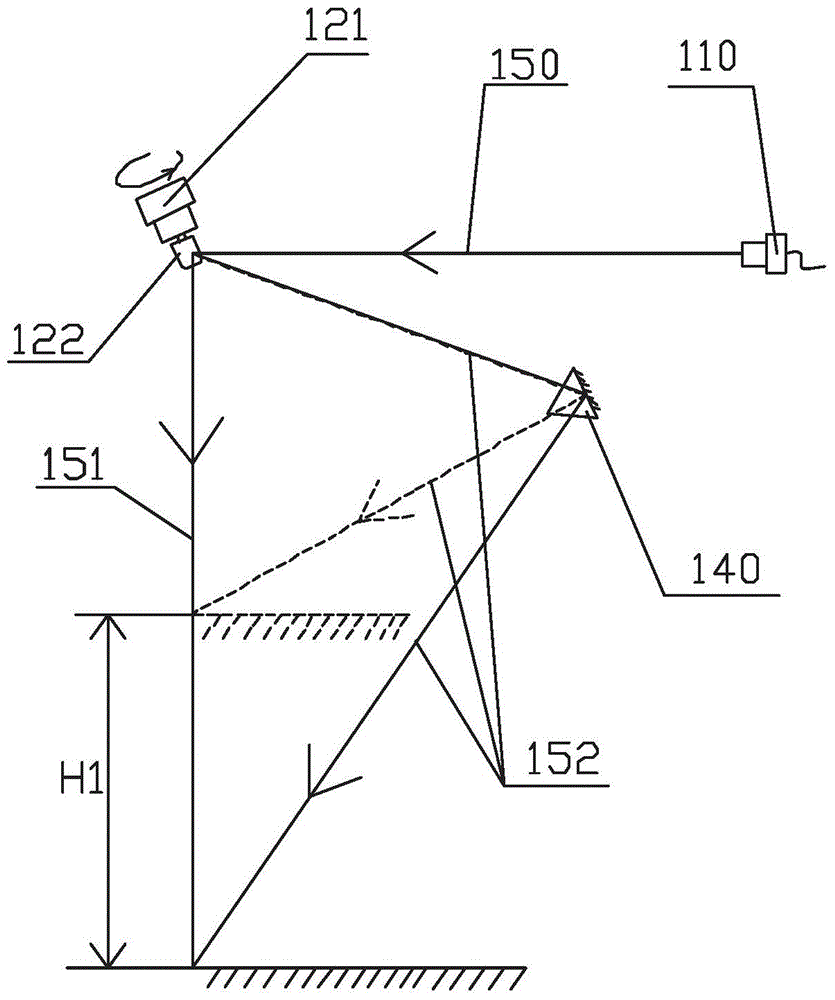
[0073] see figure 1 The indicating device in this embodiment includes a visible light indicator 110, a light splitting unit 122 driven by a high-speed motor 121, and a control unit. The visible light indicator 110 emits a visible light beam 150, and the light splitting unit 122 is arranged in the line of the visible light beam 150, so The light splitting unit 122 can reciprocate at high speed between the first position and the second position. The light splitting unit 122 is used to reflect the visible light beam 150 emitted by the visible light indicator 110. The visible light beam 150 is reflected from the reference at the first position. The beam 151 is reflected by the deflected beam 152 at the second position, and the reference beam 151 and the deflected beam 152 can be seen as two beams by the naked eye due to the high-speed reciprocating movement of the beam splitting unit 122 .
[0074] The optical path of the deflected beam 152 is provided with a reflective unit 140, ...
Embodiment 2
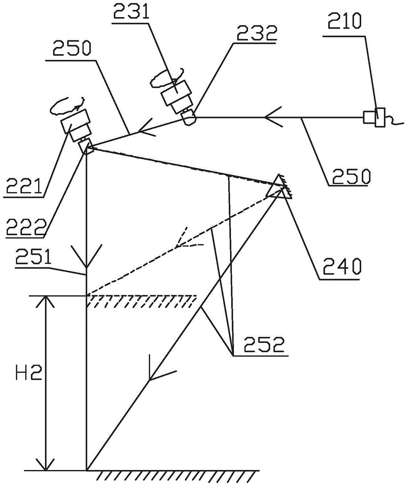
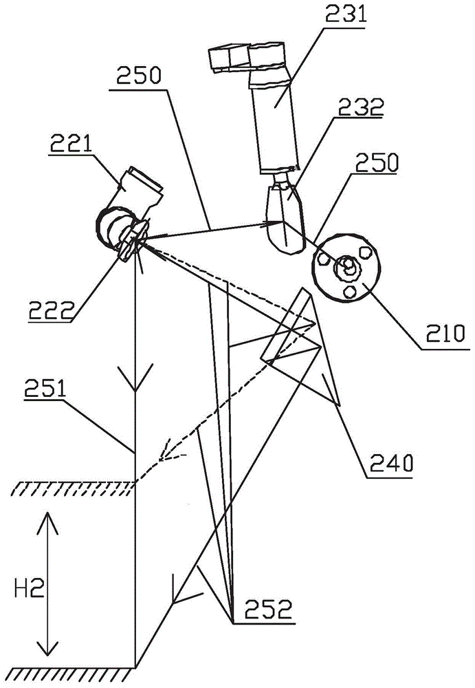
[0078] The first embodiment above can complete the laser marking height indication work, but due to factors such as installation errors, personnel operation deviations, and circuits, the reference beam and the deflected beam may not be in the same plane, and the two beams do not have an intersection point. At this time, you can It is accomplished through this embodiment.
[0079] see Figure 2 to Figure 5 The difference between this embodiment and Embodiment 1 is that in this embodiment, a second reflector 232 driven by a second motor 231 is provided between the visible light indicator 210 and the spectroscopic unit 222, and the spectroscopic unit driven by the high-speed motor 221 The unit 222 and the second reflector 232 have an included angle in space, and the visible light beam 250 can be moved at any position on a plane after being reflected by the second reflector 232 and the spectroscopic unit 222; When the second reflector 232 reflects the visible light beam 250 twice...
Embodiment 3
[0090] see Image 6 , the structure of this embodiment is similar to that of Embodiment 1, including a visible light indicator 310 capable of emitting a visible light beam 350, and a spectroscopic unit 322 moved by a high-speed motor 321. In the optical path, that is, the reference beam 351 reflected by the beam splitting unit 322 at the first position is reflected by the reflecting unit 340 and then directed to the deflected beam 352 .
PUM
| Property | Measurement | Unit |
|---|---|---|
| Wavelength range | aaaaa | aaaaa |
Abstract
Description
Claims
Application Information
 - R&D
- Intellectual Property
- Life Sciences
- Materials
- Tech Scout
- Unparalleled Data Quality
- Higher Quality Content
- 60% Fewer Hallucinations
Browse by: Latest US Patents, China's latest patents, Technical Efficacy Thesaurus, Application Domain, Technology Topic, Popular Technical Reports.
© 2025 PatSnap. All rights reserved.Legal|Privacy policy|Modern Slavery Act Transparency Statement|Sitemap|About US| Contact US: help@patsnap.com