Working method of rodlike section bar bundling robot
A working method and robot technology, which is applied to the parts, containers, and binding objects of the binding machine, can solve the problems of the wire rod being stuck, the friction coefficient is small, and the flexibility of the iron wire rod is not high, so as to achieve uniform force, good softness
- Summary
- Abstract
- Description
- Claims
- Application Information
AI Technical Summary
Problems solved by technology
Method used
Image
Examples
Embodiment Construction
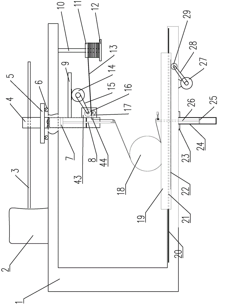
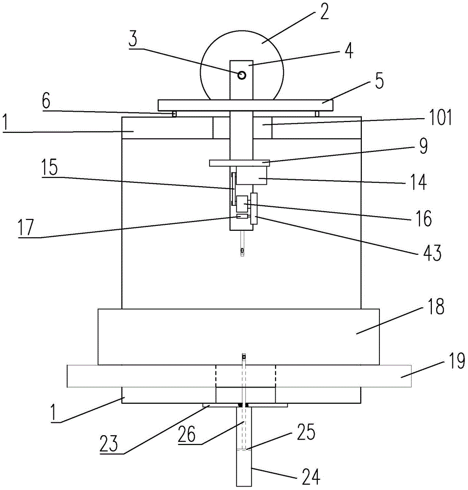
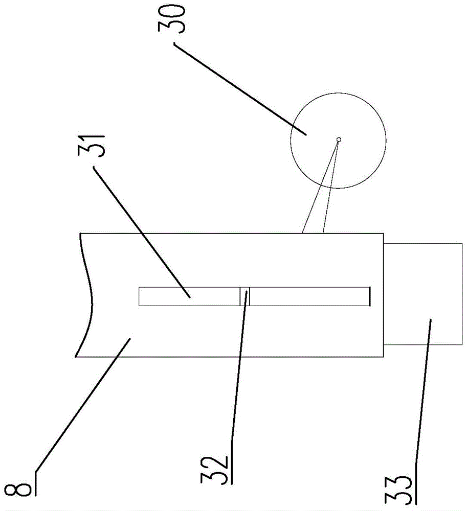
[0028] Such as figure 1 , figure 2 As shown, the rod profile bundling robot includes: a frame 1, a motor 2, a screw 3, a cylinder 4, a support plate 5, a roller 6, a piston 7, a connecting rod 8, a support 9, and a cantilever 10 , wire reel 11, bottom bracket 12, rubber belt 13, motor 2 14, belt 1 15, guide wheel 16, pulley 1 17, steel bundle 18, table top 19, sliding bar 20, sliding groove 21, rack 22, fixed plate 23, cylinder 2 24, piston 2 25, connecting rod 2 26, motor 3 27, belt 2 28, gear 29, pulley 2 30, through hole 1 31, sliding pin 32, nail box 33, pressure block 34, spring 1 35 , spring two 36, nail 37, blade 38, pressing block 39, screw rod two 40, motor four 41, support two 42, support seat 43, pulley three 44.
[0029] The opening direction of the U-shaped frame 1 on the front faces to the right, such as Figure 8 As shown, the upper arm and the lower arm are all provided with a U-shaped hole 101; the motor one 2 is fixed on the top of the upper arm of the fr...
PUM
 Abstract
Description
Claims
Application Information
 - R&D
- Intellectual Property
- Life Sciences
- Materials
- Tech Scout
- Unparalleled Data Quality
- Higher Quality Content
- 60% Fewer Hallucinations
Browse by: Latest US Patents, China's latest patents, Technical Efficacy Thesaurus, Application Domain, Technology Topic, Popular Technical Reports.
© 2025 PatSnap. All rights reserved.Legal|Privacy policy|Modern Slavery Act Transparency Statement|Sitemap|About US| Contact US: help@patsnap.com


