Bundling robot

A robot and frame technology, which is applied to the parts, containers, and strapping materials of strapping machinery. It can solve the problems of small friction coefficient, stuck wire rods, loose bundles, etc., and achieve the effect of good flexibility and uniform force.

Inactive Publication Date: 2015-04-29
DONGGUAN UNIV OF TECH
View PDF7 Cites 3 Cited by
  • Summary
  • Abstract
  • Description
  • Claims
  • Application Information

AI Technical Summary

Problems solved by technology

[0002] Most of the bar and profile bundling robots in the prior art use iron wire rods to pack steel bundles. Since this kind of wire rods have a relatively large minimum bending radius, when bundling steel bundles with small diameters , it will cause the wire rod to be stuck very late and cannot continue to be tightened, resulting in the phenomenon of virtual wir...

Method used


Image

  • Bundling robot
  • Bundling robot
  • Bundling robot

Examples


Embodiment Construction

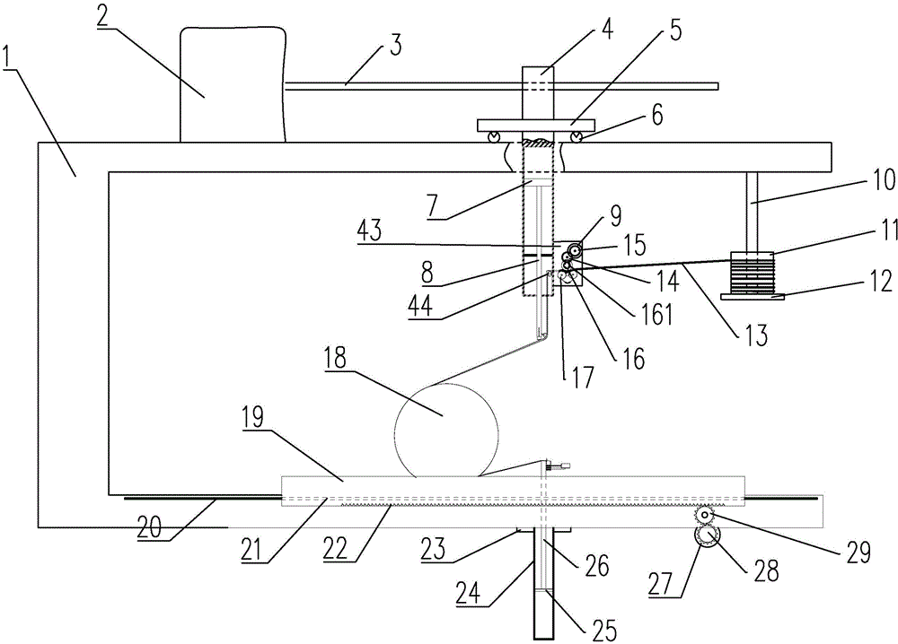
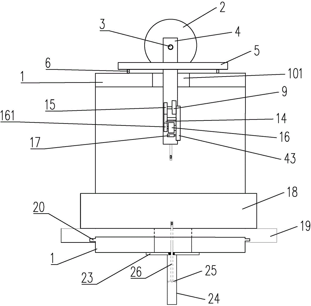
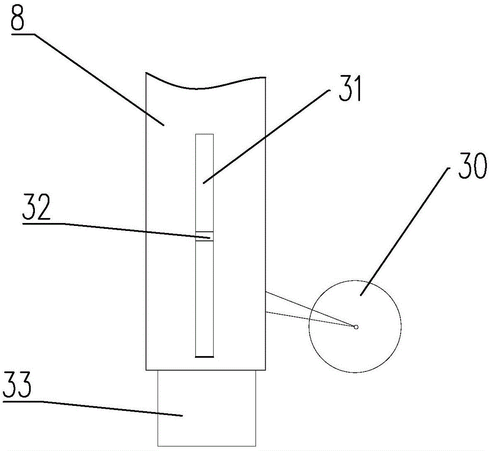
[0038] Such as figure 1 , figure 2 As shown, the rod profile bundling robot includes: frame 1, motor one 2, screw rod one 3, cylinder one 4, support plate 5, roller 6, piston one 7, connecting rod one 8, motor two 9, cantilever 10 , wire reel 11, bottom bracket 12, rubber belt 13, intermediate gear 14, driving gear 15, guide wheel 16, pulley 17, steel bundle 18, table top 19, sliding bar 20, sliding groove 21, rack 22, fixed plate 23, cylinder 2 24, piston 2 25, connecting rod 2 26, motor 3 27, belt 2 28, gear 29, pulley 2 30, through hole 1 31, sliding pin 32, nail box 33, pressure block 34, spring 1 35 , spring two 36, nail 37, blade 38, pressing block 39, screw rod two 40, motor four 41, support two 42, support seat 43, pulley three 44.

[0039] The opening direction of the U-shaped frame 1 on the front faces to the right, such as Figure 8As shown, the upper arm and the lower arm are all provided with a U-shaped hole 101; the motor one 2 is fixed on the top of the uppe...


PUM


Abstract

The invention relates to a rod section bar bundling robot. The rod section bar bundling robot comprises a machine frame, wherein an upper arm and a lower arm are arranged on the machine frame; an air cylinder I is arranged on the upper arm and is suitable for moving left and right relative to the upper arm, a piston I and a connecting rod I in the air cylinder I are suitable for vertically moving, and a telescopic nail box is arranged at the bottom end of the connecting rod I; a table board for placing a steel bundle is arranged on the lower arm in a left-right sliding fit manner, an air cylinder II is fixedly arranged at the bottom of the lower arm, a piston II and a connecting rod II at the top of the piston II are arranged in the air cylinder II, a pair of grooves is formed in the top surface of the connecting rod II, and the grooves are suitable for allowing nails to penetrate through and tightly grasp a rubber tape for bundling the steel bundle when the connecting rod I and the connecting rod II are aligned and pressed; a pressing block which is suitable for moving relative to the connecting rod II and is used for clamping ends of the rubber tape is arranged on the right side of the connecting rod II. For the rod section bar bundling robot, during the process of bundling, a virtual-wire phenomenon cannot occur, and once bundling is finished, the steel bundle is not easy to loosen due to displacement of steel wires.

Description

technical field [0001] The invention relates to a rod and profile bundling robot, which is used for bundling and packing steel materials. Background technique [0002] Most of the bar and profile bundling robots in the prior art use iron wire rods to pack steel bundles. Since this kind of wire rods have a relatively large minimum bending radius, when bundling steel bundles with small diameters , it will cause the wire rod to be stuck very late and cannot continue to be tightened, resulting in the phenomenon of virtual wires, which will cause the phenomenon of loose binding; However, since the shapes of steel bundles are different, and since the wire rod and steel are made of the same material, the friction coefficient between each other is small, and the steel bundle after tightening will also appear in the hoisting process due to the displacement of one of the steel rods. A loose bundle appears. Contents of the invention [0003] The technical problem to be solved by th...

Claims


Application Information

Patent Timeline
IPC IPC(8): B65B13/02B65B13/18B65B13/34B65B27/10
CPCB65B13/02B65B13/04B65B13/18B65B13/22B65B13/34B65B27/10
Inventor 王建芳薛国平谭建华苗兆利王耀辉
Owner DONGGUAN UNIV OF TECH
Why Eureka
Try Eureka