
Simple mechanical arm stacking machine

A technology of manipulator and palletizer, applied in the field of simple manipulator palletizer, can solve the problems of large floor space, complex equipment structure and high cost, achieve tidy palletizing specifications, improve palletizing efficiency, and reduce failure rate Effect

Inactive Publication Date: 2015-04-29
王超
View PDF5 Cites 5 Cited by
  • Summary
  • Abstract
  • Description
  • Claims
  • Application Information

AI Technical Summary

Problems solved by technology

High-level palletizing has disadvantages such as complex equipment structure, high failure rate, large floor area, and inflexible palletizing mode change.
For 4-axis robot palletizing, since the RV precision reducer, the key component of the robot, has not yet been produced in China, or domestic products cannot meet the strict accuracy requirements, most companies have to import parts or complete machines.
As a result, the price of the 4-axis robot is extremely high. A set of equipment is about 800,000 yuan. Even if the domestic robotic arm is used, almost all of its key components are imported, so the cost is also very high. The price of a set of such equipment is also 500,000 yuan. Yuan or so
Moreover, due to the explosive growth of demand for robots in China in recent years, the import delivery period of RV precision reducers has been extended from one month to four and a half months or longer, seriously affecting the delivery period of equipment and products. after-sales service
[0005] This shows that above-mentioned existing palletizer obviously still has inconvenience and defect in structure and use, and urgently needs to be further improved

Method used


Image

  • Simple mechanical arm stacking machine
  • Simple mechanical arm stacking machine

Examples


Embodiment Construction

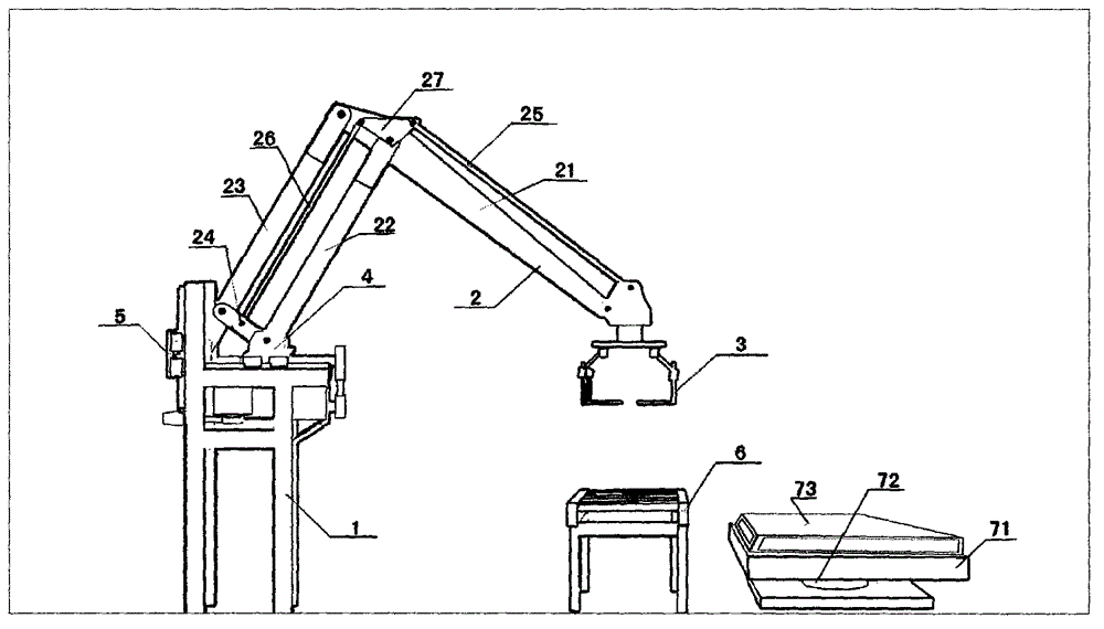
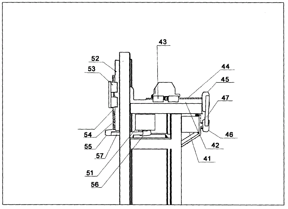
[0023] see figure 1 As shown, a simple mechanical arm palletizer of the present invention mainly includes a frame 1, a mechanical arm 2, a mechanical gripper 3, a horizontal driving mechanism 4 and a vertical driving structure 5.

[0024] Wherein, mechanical arm comprises main arm 21, forearm 22, rear arm 23 and front and rear arm connecting rod 24, and forearm 22 is parallel to rear arm 23, and forms parallelogram with the rear end of front and rear arm connecting rod 24 and main arm 21. The mechanical gripper 3 is installed at the front end of the main arm 21, and the horizontal driving mechanism 4 and the vertical driving mechanism 5 are installed on the frame 1, and drive the movement and action of the mechanical arm. Through the action of the front and rear arm links 24, the movement of either the forearm 22 or the rear arm 23 will drive the corresponding movement of the other. According to the principle of parallel hanging, the mechanical gripper 3 at the front end of th...


PUM


Abstract

The invention relates to a simple mechanical arm stacking machine. The machine comprises a rack, a mechanical arm, a mechanical grip, a horizontal driving mechanism and a vertical driving structure, wherein the mechanical arm comprises a main arm, a front arm, a rear arm and a front and rear arm connecting rod; the front arm is parallel to the rear arm and forms a parallelogram with the front and rear arm connecting rod and the rear end part of the main arm; the mechanical grip is arranged at the front end of the main arm; the horizontal driving mechanism and the vertical driving structure are both arranged on the rack and are used for driving the movement and the action of the mechanical arm. By using two-axis control, the production precision requirement and cost are reduced, the failure rate of equipment is obviously reduced, the labor is saved and the stacking efficiency is improved while automatic stacking of the mechanical arm is realized, and the stacking machine is applicable to widespread application.

Description

technical field [0001] The invention relates to the technical field of cargo palletizing, in particular to a simple mechanical arm palletizer. Background technique [0002] At present, the palletizing of bagged goods is divided into two forms: manual palletizing and mechanical palletizing. Manual palletizing is time-consuming and laborious, and it is a heavy manual labor. Especially when the weather is slightly hot, workers' physical strength is seriously overdrawn, and they have gradually withdrawn from the palletizing market. Therefore, the popularity of mechanical palletizing will be an inevitable trend in the palletizing industry. There is almost no manual palletizing in the country, and all of them are replaced by mechanical palletizing. [0003] With the rapid development of my country's economy and the improvement of people's living standards, in recent years, my country has gradually experienced a shortage of labor force, especially the shortage of rough and stupid ...

Claims


Application Information

Patent Timeline
Patent Type & Authority Applications(China)
IPC IPC(8): B65G61/00
CPCB65G61/00
Inventor 王超
Owner 王超
Learn More