Glassed steel equipment sintering rack

A glass-lined and equipment technology, applied in the field of manufacturing special appliances for chemical equipment, can solve the problems of difficult production, easy deformation during firing, and high cost

Inactive Publication Date: 2015-04-29
TIANJIN KEBI MICRO POWDER TECH
View PDF0 Cites 0 Cited by
  • Summary
  • Abstract
  • Description
  • Claims
  • Application Information

AI Technical Summary

Problems solved by technology

[0003] Inconvenient, easily deformed during firing, low product qualification rate, difficult to manufacture, high cost, slow temperature rise, many fire blocks, and unsatisfactory firing quality. The present invention proposes a firing frame for glass-lined equipment.

Method used


Image

  • Glassed steel equipment sintering rack
  • Glassed steel equipment sintering rack
  • Glassed steel equipment sintering rack

Examples


Embodiment Construction

[0017] The present invention will be described in further detail below in conjunction with the accompanying drawings and specific embodiments.

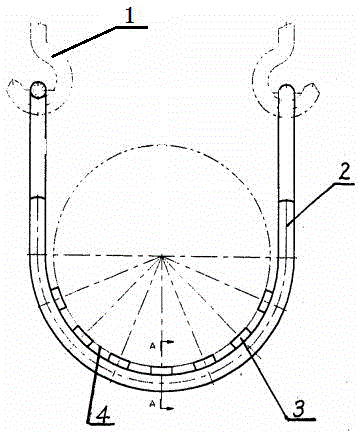
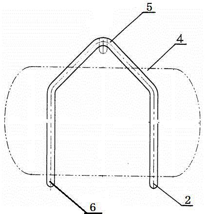
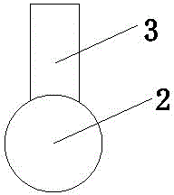
[0018] Such as Figure 1~3 As shown, a glass-lined equipment firing rack according to an embodiment of the present invention is composed of a hook 1, a first support body 2, a support plate 3, a glass-lined equipment 4, a hook 5, and a second support body 6; The two ends of the hook 5 are respectively connected with the first support body 2 and the second support body 6 to form a closed device; a support plate 3 is vertically provided between the first support body 2 and the second support body 6; The glass equipment 4 is connected with the support plate 3; the hook 1 is used to hook the hook 5 of the firing rack, and the glass-lined equipment 4 is hung up for firing.

[0019] As a preference, the hook 5 is airtightly connected with the first support body 2 and the second support body 6 in an arc-shaped triangle shape, and the...


PUM


Abstract

A glassed steel equipment sintering rack is composed of hooks, a first support body, a support plate, glassed steel equipment, a suspension hook and a second support body. Two ends of the suspension hook are respectively connected with the first support body and the second support body so as to form a closed device. The support plate is vertically arranged between the first support body and the second support body. The glassed steel equipment is connected with the support plate. The hooks are used for hooking the suspension hook of the sintering rack so as to hoist the glassed steel equipment for sintering. The glassed steel equipment sintering rack provided by the invention has advantages of simple structure, light weight, easy manufacturing, low cost, few fire blocking, fast temperature rising and good sintering quality.

Description

technical field [0001] The invention belongs to the field of special utensils for manufacturing chemical equipment, in particular to a glass-lined equipment firing frame and relates to a special utensil for glass-lined equipment firing. Background technique [0002] At present, the firing of chemical equipment, especially glass-lined equipment, is mainly carried out in the firing furnace of glass-lined equipment. Due to the large size and heavy weight of this equipment, it has been used for many years to directly transport it together with the conveyor frame The firing method is completed in the hearth of the firing furnace. This firing method has been used for many years. The main problems are that the temperature rises slowly, the glass-lined equipment is easily deformed, the product qualification rate is low, and the loading and unloading is inconvenient. The main feature of the furnace is that it is equipped with a movable firing furnace bottom, and a firing frame is pla...

Claims


Application Information

Patent Timeline
Patent Type & Authority Applications(China)
IPC IPC(8): C23D9/08C23D9/10
Inventor 不公告发明人
Owner TIANJIN KEBI MICRO POWDER TECH
Why Eureka
Try Eureka