
Air distribution mechanism with concave shaft

A concave shaft valve mechanism and concave shaft technology, applied in exhaust devices, mechanical equipment, engine components, etc., can solve the problems affecting the engine compression ratio and complex structure, and achieve the effect of increasing the compression ratio and simple structure

Inactive Publication Date: 2015-04-29
陈 月
View PDF6 Cites 0 Cited by
  • Summary
  • Abstract
  • Description
  • Claims
  • Application Information

AI Technical Summary

Problems solved by technology

[0003] The existing engine valve mechanism is generally composed of a series of parts such as valves, valve guides, springs, valve spring seats, push rods, tappets, and camshafts. The number of parts is large and the structure is complex. By opening the intake valve and exhaust The valve is used to control the entry of fresh gas and the discharge of exhaust gas, and because the lift of the valve requires a certain distance, it will affect the compression ratio of the engine in some valve arrangements.

Method used


Image

  • Air distribution mechanism with concave shaft
  • Air distribution mechanism with concave shaft
  • Air distribution mechanism with concave shaft

Examples


Embodiment Construction

[0021] The concave shaft valve mechanism of the present invention will be further explained below in conjunction with the accompanying drawings.

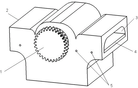
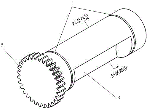
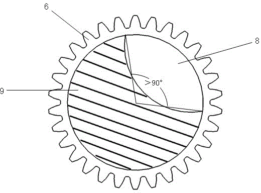
[0022] The side of the concave shaft gas distribution cylinder head with spark plug is the intake channel, and the other side is the exhaust channel. The concave shaft through hole and the shrapnel positioning pin hole of the cylinder head are processed in the direction perpendicular to the front and rear. A positioning seal ring groove is processed on the through hole, a rectangular gas main passage is processed between the cylinder head concave shaft through hole and the cylinder, and the spark plug is installed on one side of the gas main passage; the concave shaft is a solid cylinder, A timing gear is welded at one end, and a concave channel is processed on one side of the shaft. On the profile of the concave shaft, the angle formed by the line connecting the concave channel and the center of the concave shaft is greater than 90 ...


PUM


Abstract

An air distribution mechanism with a concave shaft consists of the concave shaft, a concave shaft air distribution cylinder cover, a sealing spring plate and a sealing positioning ring, wherein the concave shaft is arranged in the concave shaft air distribution cylinder cover by matching the sealing spring plate and the sealing positioning ring; and during air distribution of an engine, fresh air can enter a cylinder and waste gas can be discharged from the cylinder when a concave-surface channel of the concave shaft is connected with an air feeding channel.

Description

Technical field: [0001] The invention relates to a gas distribution mechanism of an automobile engine. [0002] Background technique: [0003] The existing engine valve mechanism is generally composed of a series of parts such as valves, valve guides, springs, valve spring seats, push rods, tappets, and camshafts. The number of parts is large and the structure is complex. By opening the intake valve and exhaust The valve is used to control the entry of fresh gas and the discharge of exhaust gas, and because the lift of the valve requires a certain distance, it will affect the compression ratio of the engine in some valve arrangements. [0004] Invention content: [0005] The concave shaft gas distribution mechanism of the present invention is composed of a concave shaft, a concave shaft gas distribution cylinder head, a sealing shrapnel and a sealing positioning ring, and the concave shaft is installed in the concave shaft gas distribution cylinder head through the c...

Claims


Application Information

Patent Timeline
IPC IPC(8): F02M35/10F01N13/00
Inventor 陈月
Owner 陈 月
Features
  • Generate Ideas
  • Intellectual Property
  • Life Sciences
  • Materials
  • Tech Scout
  • Unparalleled Data Quality
  • Higher Quality Content
  • 60% Fewer Hallucinations
Learn More