Valve Block having a Valve Assembly

A technology of valve device and valve group, which is applied in the direction of fluid pressure actuation device, transportation and packaging, servo motor components, etc., which can solve the problems of high structural space requirements and achieve the effect of reducing costs

Active Publication Date: 2015-04-29
ROBERT BOSCH GMBH
View PDF7 Cites 0 Cited by
  • Summary
  • Abstract
  • Description
  • Claims
  • Application Information

AI Technical Summary

Problems solved by technology

Afterwards, the pressure relief valve is also flow-through when the pressure reduction should not be carried out due to the high pressure loss that would result
In addition, the high installation space requirement is extremely disadvantageous

Method used


Image

  • Valve Block having a Valve Assembly
  • Valve Block having a Valve Assembly
  • Valve Block having a Valve Assembly

Examples


Embodiment Construction

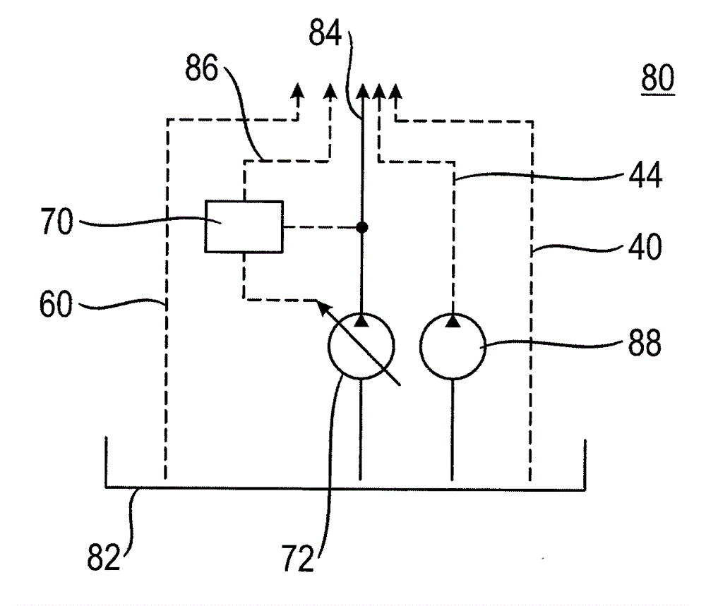
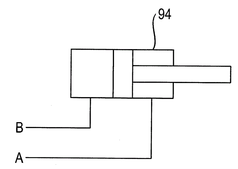
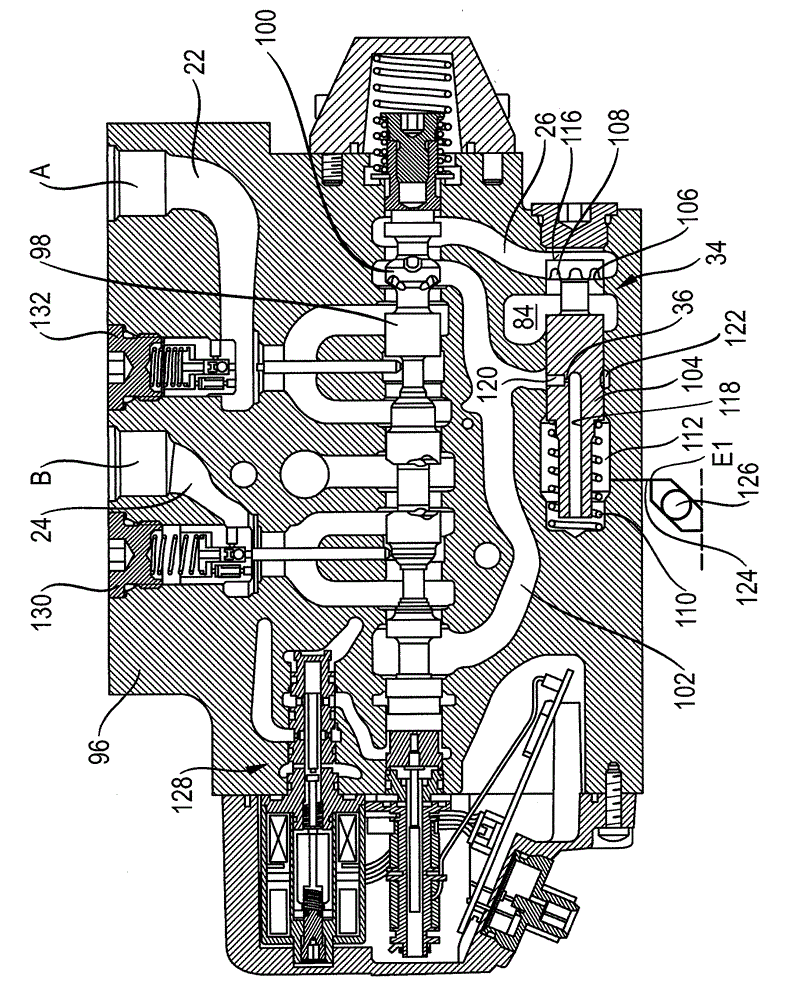
[0036] according to figure 1 A valve arrangement 1 according to the invention in the form of a valve block 2 is shown. It has a plurality of control valve disks 10 to 12 and a pressure limiting valve disk 14 . The control valve disks 4 to 8 in this case form a first group part 16 and the control valve disks 10 and 12 form a second group part 18 . A consumer can be connected to the respective control valve disk 4 to 12 via the working ports A and B. To control the speed and direction of the respective consumer, the respective control valve disk 4 to 12 has a control valve 20 , wherein only the control valve 20 of the control valve disk 4 is shown with reference numerals for the sake of overview.

[0037] Since the control valve disks 4 to 12 are designed identically, the structure of the corresponding control valve disks 4 to 12 will be explained in detail with reference to the control valve disk 4 . The working port A of the control valve disk 4 is connected to the control ...


PUM


Abstract

A valve block includes a plurality of control valve disks that form a first block part and a second block part. A supply pressure for the control valve disks of the first block part is limited by a common pressure-limiting valve. The common pressure-limiting valve is arranged such that a prevailing load pressure registered by the control valve disks does not exceed a specific value. The supply pressure for the control valve disks of the second block part is not limited.

Description

technical field [0001] The invention is based on a valve arrangement and a valve block according to the preamble of claim 1 . Background technique [0002] Such hydraulic valve arrangements or control systems are known from the prior art and have so-called "load sensing" control valves with a control piston for direction control and speed control. A metering flap is formed in the control piston. In this case, the respective control valve is associated with a pressure balance, which keeps the pressure drop over the respective metering flap and the volume flow constant, independent of the load. For this, the pressure upstream and downstream of the metering flap is measured and reported to the pressure balance. In the normally open neutral position, the piston of the pressure balance is prestressed by a spring which exerts an ideally constant force. In addition to the spring, the load pressure tapped downstream of the metering flap acts in the opening direction of the piston...

Claims


Application Information

Patent Timeline
Patent Type & Authority Applications(China)
IPC IPC(8): F15B11/16F15B13/06
CPCF15B11/165F15B13/0417F15B2211/654F15B2211/6051F15B2211/6054F15B2211/6055F15B2211/7142F15B2211/3127F15B2211/30535F15B2211/20546F15B13/0817Y10T137/2544G05D16/106
Inventor S.克纳佩尔
Owner ROBERT BOSCH GMBH
Why Eureka
Try Eureka