
Singe- and double-stage overlapped type air source heat pump heating system

An air source heat pump and heating system technology, which is applied in lighting and heating equipment, gas cycle refrigerators, compressors with cascade operation, etc., can solve the problems of high cost, low energy efficiency ratio, air source heat pump limitation, etc. Achieve the effect of increasing COP value and reducing heat dissipation loss

Inactive Publication Date: 2015-04-29
北京中兵同泰能源科技有限公司
View PDF2 Cites 6 Cited by
  • Summary
  • Abstract
  • Description
  • Claims
  • Application Information

AI Technical Summary

Problems solved by technology

The air source heat pump adopts technical measures to improve the low-temperature operation characteristics, which can greatly delay the attenuation of the heating capacity with the outdoor temperature, and can even operate when it is lower than -20°C, but measured from the heating efficiency and the energy efficiency ratio of the system, in When the temperature is lower than -10°C, the outlet air temperature and performance of the air source heat pump system can no longer give full play to the advantages of heat pump technology
[0004] In order to solve the problem of low performance of the air source heat pump system under low temperature conditions, those skilled in the art mainly adopted measures such as increasing the capacity of the compressor, increasing the area of ​​the outdoor heat exchanger, or applying liquid spray bypass, gas injection, frequency conversion However, due to the complex system, high process requirements, low efficiency, high cost, and low COP (energy efficiency ratio) value, the application of air source heat pumps is greatly limited.
In recent years, air source heat pump technology has also been widely used in my country. In the Yangtze River Basin of China, the climate is hot in summer and cold in winter. In the northern region, due to the low outdoor temperature in winter, the air source heat pump technology has not been widely used.

Method used


Image

  • Singe- and double-stage overlapped type air source heat pump heating system

Examples


Embodiment Construction

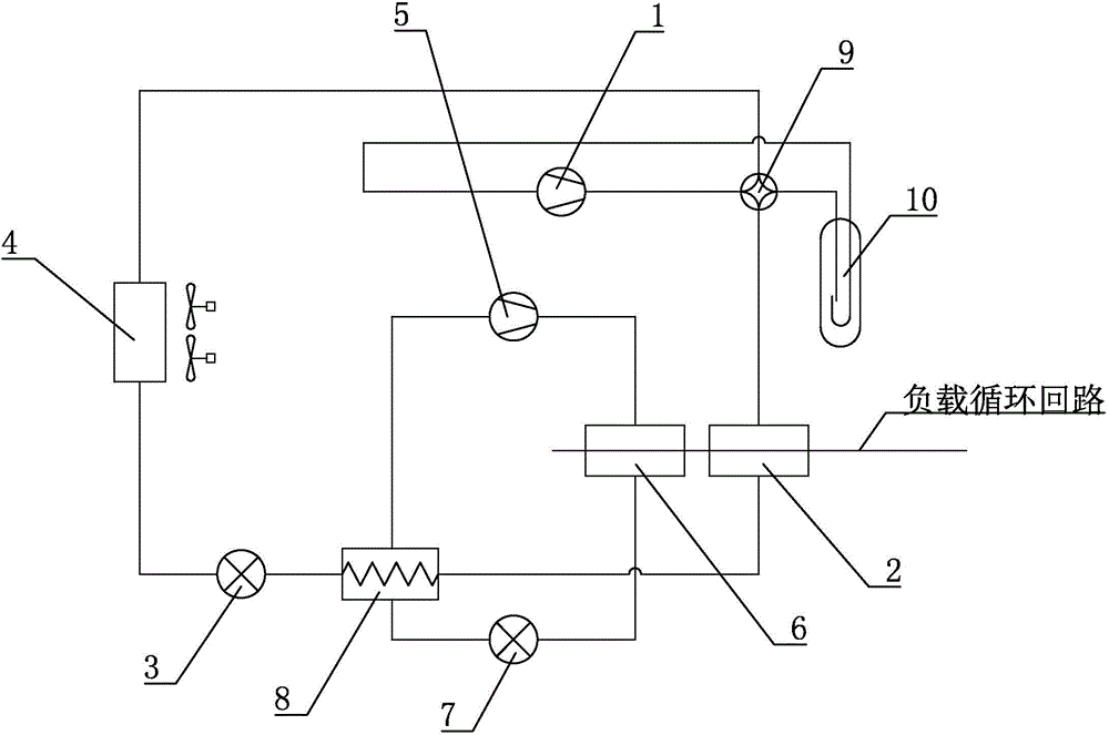
[0016] like figure 1 Shown is a specific embodiment of a single- and double-stage cascade air source heat pump heating system of the present invention, including a low-temperature stage heat pump unit and a high-temperature stage heat pump unit, and the low-temperature stage heat pump unit is equipped with a low-temperature stage compressor 1 and a low-temperature stage condenser 2. Low-temperature level throttle valve 3 and low-temperature level evaporator 4; high-temperature level heat pump unit is equipped with high-temperature level compressor 5, high-temperature level condenser 6, high-temperature level throttle valve 7 and high-temperature level evaporator 8; low-temperature level heat pump unit Coupling heat exchange with the high-temperature heat pump unit at the high-temperature evaporator 8; coupled heat exchange with the low-temperature heat pump unit and the high-temperature heat pump unit at the low-temperature condenser 2 and high-temperature condenser 6 respectiv...


PUM


Abstract

The invention relates to a single- and double-stage overlapped type air source heat pump heating system. The system comprises a low-temperature-stage heat pump unit and a high-temperature-stage heat pump unit; the low-temperature-stage heat pump unit is equipped with a low-temperature-stage compressor, a low-temperature-stage condenser, a low-temperature-stage throttling valve and a low-temperature-stage evaporator; the high-temperature-stage heat pump unit is equipped with a high-temperature-stage compressor, a high-temperature-stage condenser, a high-temperature-stage throttling valve and a high-temperature-stage evaporator; the low-temperature-stage heat pump unit and the high-temperature-stage heat pump set are coupled at the high-temperature-stage evaporator to exchange heat; a load circulating circuit is respectively coupled with the low-temperature-stage heat pump unit and the high-temperature-stage heat pump unit at the low-temperature-stage condenser and the high-temperature-stage condenser to exchange heat. The system has the advantages of being high in structure, low in cost, high in efficiency, and high in energy efficiency ratio.

Description

technical field [0001] The invention relates to the field of heat pump air conditioners, in particular to a single- and double-stage cascade air-source heat pump heating system. Background technique [0002] The traditional heating method mainly consumes high-level energy such as gas or coal, provides low-temperature heat to the interior of the building through the boiler and circulation system, and discharges waste heat, waste gas, waste residue and other wastes to the environment. Based on the urgent requirements of saving energy and avoiding environmental pollution, this one-way heating method can no longer meet the needs of coordinated development of energy, heating and the environment. At present, heat pump technology is mainly used in this technical field to solve the problem of coordinated development of HVAC system energy consumption and environment. The development and application of heat pump technology has become an important technical means for the sustainable de...

Claims


Application Information

Patent Timeline
IPC IPC(8): F25B7/00F25B43/00F25B41/04F25B47/00F25B49/02F25B41/20
CPCF25B7/00F25B43/00F25B47/00F25B49/022F25B2313/02741F25B2309/14F25B41/20
Inventor 杨自强
Owner 北京中兵同泰能源科技有限公司
Learn More