Bilateral fitting confocal measuring method

A measurement method and confocal technology, applied in measurement devices, instruments, optical devices, etc., can solve the problem of confocal microscope resolution limitation and other problems, and achieve improved axial resolution, improved signal-to-noise ratio, and high signal-to-noise ratio. Effect

Active Publication Date: 2015-04-29
BEIJING INSTITUTE OF TECHNOLOGYGY
View PDF5 Cites 19 Cited by
  • Summary
  • Abstract
  • Description
  • Claims
  • Application Information

AI Technical Summary

Problems solved by technology

[0007] However, the existing confocal microscopes mainly use data that is relatively insensitive to the position of the focal plane near the extreme point to perform curve fitting to find the position of the extreme point, that is, the position of the focal plane. Therefore, the further improvement of the resolving power of the existing confocal microscope is restricted.

Method used


Image

  • Bilateral fitting confocal measuring method
  • Bilateral fitting confocal measuring method
  • Bilateral fitting confocal measuring method

Examples


Embodiment 1

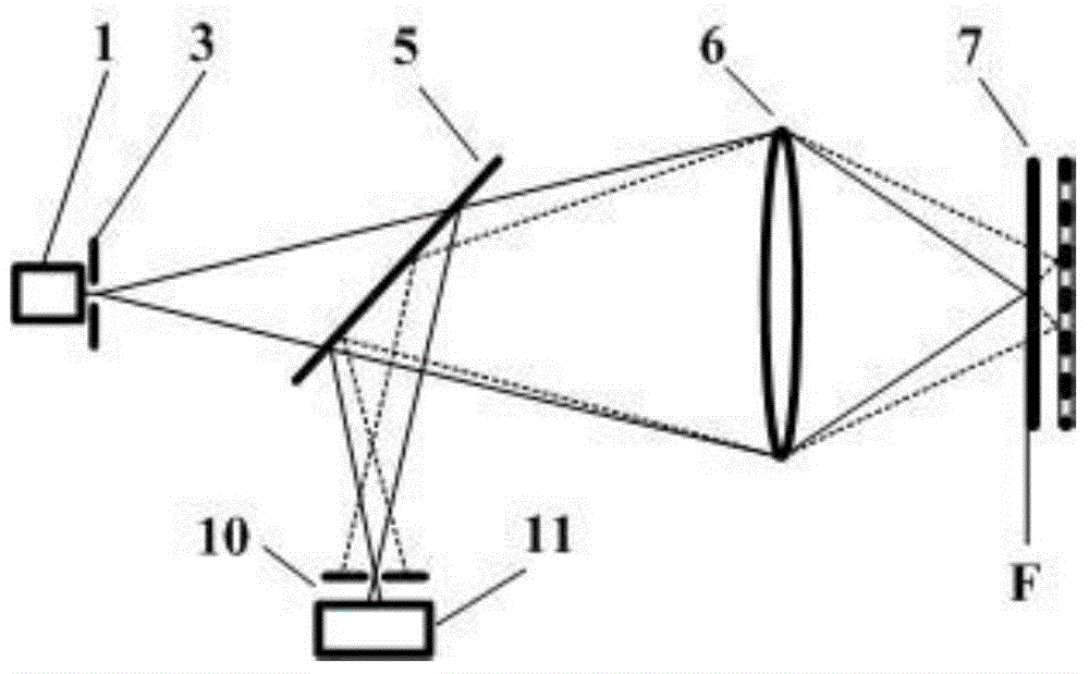
[0036] Combination of specific steps for carrying out single-point height value fitting measurement using the method of the present invention Figure 5 described as follows:

[0037] Step 1. Select a certain measurement point N(x,y) on the sample 7, make the objective lens 6 focus the light spot to scan the measurement point axially, and at the same time, the photodetector detection 11 detects the confocal axial intensity of the axial position of the sample The response value is 14, denoted as I(z), where x, y and z are the coordinates of the horizontal position and the axial height position of the sample measurement point respectively;

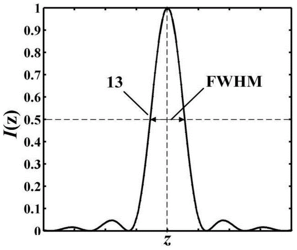
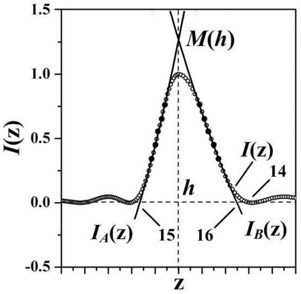
[0038] Step two, such as Figure 4 As shown, find the maximum value M of the confocal axial intensity response value 14;

[0039] Step three, such as Figure 4 As shown, on both sides of the confocal axial intensity response data, the data point whose intensity is M / 2 point is used as a reference point to select a data segment near it;

...

Embodiment 2

[0044] Under the scanning of the sample workbench, the method of the present invention is used to combine the measurement steps of point-by-point tomographic scanning imaging Figure 5 described as follows:

[0045] Step 1, move the workbench 8, write down the horizontal position coordinates N(x, y) of the measured point of the sample 7;

[0046] Step 2: Feed the objective lens 6 in axial steps relative to the sample 7 along the optical axis, and the photodetector 11 measures the confocal axial intensity response value 14 corresponding to each axial feeding position;

[0047] Step three, such as Image 6 As shown, use the computer measurement and control system 12 to extract the maximum value point position M corresponding to the measured interface in the sequence photoelectric signal value measured in step 2 k ;

[0048] Step 4, such as Image 6 As shown, take a section of data points at the positions where the steepness changes on both sides of each maximum point obtaine...

Embodiment 3

[0054] Under the scanning of the sample workbench, the measurement steps of layer-by-layer scanning tomography using the method of the present invention are combined Figure 5 described as follows:

[0055] Step 1. Focus the objective lens 6 on the first interface of the sample to be tested, and then move the workbench 8. In this interface, the photodetector 11 measures the photoelectric signal values ​​of all the points to be measured, and simultaneously records the levels of all points to be measured. Position coordinates;

[0056] Step 2. According to the measurement accuracy requirements of the sample, select the micro-feeding step of the objective lens relative to the sample;

[0057] Step 3: Feed the objective lens 6 relative to the sample 7 in small steps along the direction of the optical axis, and then accurately move the worktable 8 according to the coordinates of the horizontal position points recorded in step 1, so that the focal spot of the objective lens is alig...


PUM


Abstract

The invention belongs to the technical field of optical imaging and detection and relates to a bilateral fitting confocal measuring method. According to the method, curve equations are respectively fit by respectively utilizing two sections of data at both sides of a confocal system characteristic curve and differential subtraction is carried out to obtain a new curve equation; by solving the new curve equation, the position of an extreme point of the confocal system characteristic curve is obtained. According to the bilateral fitting confocal measuring method, two sections of data, which are close to the half-width position of the confocal system characteristic curve and are very sensitive for the axial displacement, are utilized to carry out fitting, and thus, compared with flexibility obtained by an existing confocal characteristic curve top fitting method, the flexibility of the position, which is calculated by the data sections, of the extreme point of the confocal system characteristic curve is greatly improved and the bilateral fitting confocal measuring method is more suitable for processing the asymmetric confocal characteristic curve in the actual measurement. The invention provides a bran-new measurement processing method for the field of confocal imaging/detection.

Description

technical field [0001] The invention belongs to the technical field of three-dimensional microscopic measurement, and relates to an axial high-resolution bilateral fitting differential confocal measurement method, which can be used to measure the three-dimensional microstructure, microsteps, microstructure grooves, integrated circuit line width and surface morphology etc. Background technique [0002] The idea of ​​confocal microscopy was first proposed by American scholar M.Minsky in 1957, and he obtained the US patent in 1961, the patent number is US3013467. The confocal microscope places the point light source, point object, and point detector in corresponding conjugate positions, forming a point illumination and point detection microscopic imaging system with unique tomographic capabilities in optical microscopic imaging. [0003] The basic principles of confocal microscopy are figure 1 As shown, the light emitted by the light source 1 passes through the pinhole 3, the...

Claims


Application Information

Patent Timeline
Patent Type & Authority Applications(China)
IPC IPC(8): G01B11/00
Inventor 赵维谦邱丽荣
Owner BEIJING INSTITUTE OF TECHNOLOGYGY
Why Eureka
Try Eureka