Final-stage channel flow measuring method and device

A flow measurement device and flow measurement technology, which are used in the detection of fluid flow by measuring differential pressure, volume/mass flow generated by mechanical effects, etc., which can solve the problems of inconvenient automatic monitoring and management, inability to continuously measure, and poor accuracy. Achieve the effect of improving efficiency and measurement accuracy, improving flow detection accuracy, and small measuring range

Inactive Publication Date: 2015-04-29
唐山现代工控技术有限公司
View PDF10 Cites 5 Cited by
  • Summary
  • Abstract
  • Description
  • Claims
  • Application Information

AI Technical Summary

Problems solved by technology

[0002] Today's agricultural production no longer depends on the weather, but on irrigation to ensure a good harvest. Channels are used to lead surface water to the fields. Canal systems are composed of large and small channels. The order is: main canal, branch canal, bucket canal, end-level canal, surface water is distributed from one main canal to multiple branch canals, one branch canal is allocated to multiple bucket canals, one bucket canal is allocated to multiple end-level canals, and the canal is the last end-level canal In the field, where the quantity is large, the flow rate is small, and the flow rate is slow, it is the place where farmers are charged for water metering. However, there is no ideal and cheap water metering product at present. The staff use hand-held propeller flowmeters to come to the field. Manual measurement of the ground is low in efficiency and accuracy, and cannot be measured continuously, and it is not convenient for automatic monitoring and management

Method used


Image

  • Final-stage channel flow measuring method and device
  • Final-stage channel flow measuring method and device
  • Final-stage channel flow measuring method and device

Examples


Embodiment 1

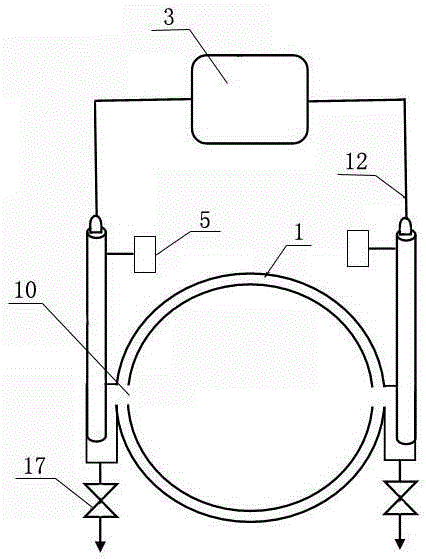
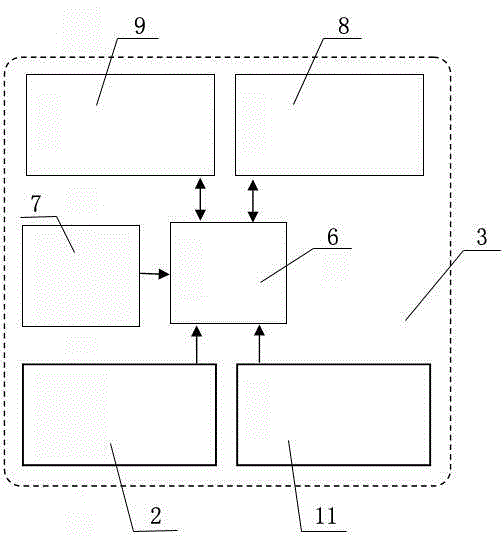
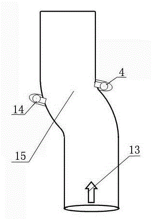
[0046] Embodiment one, with reference to the attached figure 1 , 2 , 3, the main pipeline 1 is a pipeline with an S-shaped curved structure 15, and the pressure-taking points of the two pressure sensors on the main pipeline are respectively arranged on the inner side and the outer side corresponding to the bending point of the main pipeline; The pressure taking points on the side are respectively provided with pressure pipes to communicate with the pressure taking points. The two pressure pipes are respectively the inner pressure pipe 4 and the outer pressure pipe 14. The two pressure sensors are pressure sensor one 2 and pressure sensor two 11 respectively. Sensor 1 2 matches the inner pressure tube 4, pressure sensor 2 11 matches the outer pressure tube 14; the pressure on the inside and outside of the bending point of the main pipeline is taken from the inner pressure tube to the pressure sensor 1, and the outer pressure tube is led to the pressure sensor 2 .

Embodiment 2

[0047] Embodiment two, referring to the attached figure 1 , 2 4. The main pipeline 1 is a pipeline with two S-shaped curved structures. The main pipeline is a V-shaped structure 16 as a whole. The bending point of the V-shaped structure is located at the bottom apex of the V-shaped structure. Two pressure sensors are on the main pipeline The pressure-taking points of the pressure sensor are respectively set on the inner side and the outer side corresponding to the bottom apex of the V-shaped structure of the main pipeline, that is, the pressure-taking point of the pressure sensor matches the middle part of the bend of the main pipeline. At the pressure taking points on both sides of the main pipeline, pressure pipes are respectively provided to communicate with the pressure taking points. The two pressure pipes are the inner pressure pipe 4 and the outer pressure pipe 14 respectively, and the two pressure sensors are pressure sensor one 2 and pressure sensor respectively. Two...


PUM


Abstract

The invention relates to a final-stage channel flow measuring method and device and belongs to the technical field of agricultural irrigation flow metering. According to the technical scheme, two pressure sensors are arranged on two sides of a main pipeline (1) in a matched manner, and the output ends of the pressure sensors are connected to a monitoring terminal (3); the pressure sampling points of the two pressure sensors are opposite on the main pipeline, one point faces to the water incoming direction of the main pipeline obliquely, and the other point is opposite to the water incoming direction of the main pipeline obliquely; the monitoring terminal comprises a single chip processor (6), a lithium-ion battery (7), a remote communication module (8) and a radio frequency communication module (9), the radio frequency communication module matches with a radio frequency communication module of mobile communication equipment, and the remote communication module matches with a remote monitoring computer. The continuous flow monitoring can be performed in the field final-stage channels, the efficiency and measuring accuracy can be improved, the problem of 'agricultural irrigation last one kilometer metering' can be solved, and the effect of saving water is achieved.

Description

technical field [0001] The invention relates to a method and device for measuring the flow rate of an end-stage channel, belonging to the technical field of agricultural irrigation flow measurement. Background technique [0002] Today's agricultural production no longer depends on the weather, but on irrigation to ensure a good harvest. Channels are used to lead surface water to the fields. Canal systems are composed of large and small channels. The order is: main canal, branch canal, bucket canal, end-level canal, surface water is distributed from one main canal to multiple branch canals, one branch canal is allocated to multiple bucket canals, one bucket canal is allocated to multiple end-level canals, and the canal is the last end-level canal In the field, where the quantity is large, the flow rate is small, and the flow rate is slow, it is the place where farmers are charged for water metering. However, there is no ideal and cheap water metering product at present. The s...

Claims


Application Information

Patent Timeline
Patent Type & Authority Applications(China)
IPC IPC(8): G01F1/34
Inventor 张喜于树利张家铭
Owner 唐山现代工控技术有限公司
Why Eureka
Try Eureka