
Device and method for measuring three-dimensional temperature field of laser-induced plasma

A technology of plasma and three-dimensional temperature, which is applied in the direction of measuring devices, measuring heat, thermometers, etc., can solve the problems of being unable to obtain accurate values ​​of the three-dimensional temperature field, unreasonable, etc., and achieve the effect of simple and fast calibration process, simple structure and convenient use

Inactive Publication Date: 2015-04-29
SHANGHAI JIAO TONG UNIV
View PDF9 Cites 5 Cited by
  • Summary
  • Abstract
  • Description
  • Claims
  • Application Information

AI Technical Summary

Problems solved by technology

This method obtains the two-dimensional temperature distribution of the plasma. To further calculate the three-dimensional temperature field, an inverse Abel transformation is required. The premise of the inverse Abel transformation is that the physical parameters of the object conform to the cylindrical symmetric distribution, but in most cases , the spatial structure of the photoplasma does not satisfy the symmetry condition, so it is unreasonable to adopt the method of inverse Abel transformation
[0006] It can be seen that for the photo-induced plasma with asymmetric distribution of spatial shape and structure generated during laser processing, none of the above methods can obtain the precise value of the internal three-dimensional temperature field.

Method used


Image

  • Device and method for measuring three-dimensional temperature field of laser-induced plasma
  • Device and method for measuring three-dimensional temperature field of laser-induced plasma

Examples


Embodiment Construction

[0021] The technical solution of the present invention will be described in detail below by taking the measurement of the three-dimensional temperature field of the photoinduced plasma during the laser welding process as a specific example.

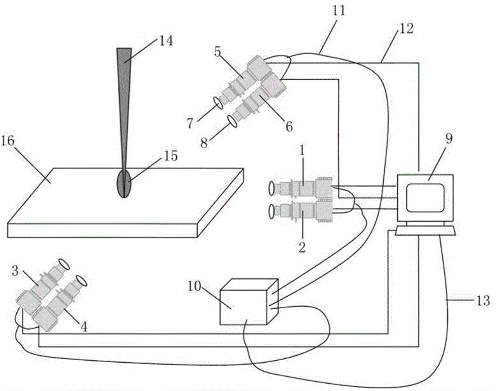
[0022] attached figure 1 The device for measuring the plasma temperature distribution outside the small hole of laser deep penetration welding for this embodiment includes a camera, a fixed bracket, a computer 9, and an external trigger device 10. The camera is a CCD camera, and the fixed bracket is used to fix the camera. The camera and the external trigger device 10 is connected with an IO signal line 11, the camera is connected with the computer 9 with an image data line 12, and the external trigger device 10 is connected with the computer 9 with an IO signal line 13. Between camera, external triggering device 10 and computer 9, also can adopt other ways to connect, can guarantee the smooth transmission of signal and image and get fina...


PUM

PropertyMeasurementUnit
temperatureaaaaaaaaaa

Abstract

The invention discloses a device and method for measuring a three-dimensional temperature field of laser-induced plasma. According to the device, a plurality of groups of cameras are arranged around the laser-induced plasma in a distributed mode, and each group of cameras includes two cameras with optical filters with different central wavelengths installed at front ends of lenses. All the cameras are triggered strictly synchronously through a synchronous external triggering device, and projection images of different angles and different characteristic spectral lines of the laser-induced plasma at the same time are obtained. The spatial brightness distribution of the two characteristic spectral lines of the laser-induced plasma is calculated based on the obtained projection images of the laser-induced plasma according to the algorithm for reconstructing the three-dimensional image of an objected by means of projection, and finally the three-dimensional temperature field of the laser-induced plasma is calculated according to the relative spectral line intensity method. The device and method have the advantages that the device is simple, the method is easy to implement, measurement precision is high, and the range of measurement objects is wide, and the device and method can be used for online detection of physical parameters of laser-induced plasma during laser processing, quality monitoring during laser processing and other aspects.

Description

technical field [0001] The invention relates to a temperature measuring device and a measuring method, in particular to a measuring device and a measuring method for a three-dimensional temperature field of photoinduced plasma, which are applied to the diagnosis and process monitoring of photoinduced plasma, and belong to the field of mechanical engineering. Background technique [0002] Photoplasma is the plasma generated by applying laser to the surface of metal workpiece. Photoplasma plays a vital role in the laser-workpiece energy interaction process, thus affecting the quality of laser processing. In the process of high-power laser welding, the high temperature generated by the laser ionizes the metal vapor to form a high-temperature and high-density photoplasma, which mainly affects the energy coupling between the laser and the material from two aspects of absorption and refraction. The spatial temperature distribution of photoinduced plasma directly reflects the dyna...

Claims


Application Information

Patent Timeline
Patent Type & Authority Applications(China)
IPC IPC(8): G01K11/30
Inventor 孙大为蔡艳朱俊杰
Owner SHANGHAI JIAO TONG UNIV
Learn More