
Testing device for measuring cold-state flow field in gas burner based on PIV (particle image velocimetry) technique

A gas burner and test device technology, applied in the field of test devices based on PIV technology, can solve problems such as doubts about the reliability and accuracy of calculation results, inability to fully learn from PIV measurement devices, and the like, and achieve the effect of avoiding disturbances

Inactive Publication Date: 2015-04-29
CHINA PETROLEUM & CHEM CORP +1
View PDF5 Cites 19 Cited by
  • Summary
  • Abstract
  • Description
  • Claims
  • Application Information

AI Technical Summary

Problems solved by technology

However, the numerical simulation results are based on various simplified conditions and hypothetical models, and the reliability and accuracy of the calculation results have been questioned.
[0011] Although PIV technology has been widely used, there are few domestic reports on the use of PIV technology to measure the cold flow field of gas burners in heating furnaces, and considering the structural characteristics of gas burners and furnaces, it is impossible to fully use PIV measurement devices in other fields

Method used


Image

  • Testing device for measuring cold-state flow field in gas burner based on PIV (particle image velocimetry) technique
  • Testing device for measuring cold-state flow field in gas burner based on PIV (particle image velocimetry) technique
  • Testing device for measuring cold-state flow field in gas burner based on PIV (particle image velocimetry) technique

Examples


Embodiment 1

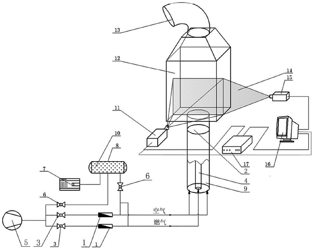
[0039] The test device designed according to the present invention takes an in-service air-staged gas burner as a prototype, processes it into a model burner with plexiglass at a ratio of 1:4 (model: prototype), and builds and measures the formation speed of the model burner in a cuboid combustion chamber. Field-specific test equipment. This embodiment is designed based on the principle of simulating a non-isothermal process with an isothermal medium, and mainly studies the influence of different nozzle structures on the shape of the flow field.

[0040] see figure 1, the test device of this embodiment, including a cold model of a heating furnace, a gas path system, a tracer particle dispersion device and a PIV test system. The cold state model of the heating furnace includes a burner 2 , a transparent combustion chamber 12 and a smoke exhaust pipe 13 , one end of the burner 2 is connected with the transparent combustion chamber 12 , and the upper part of the transparent com...

Embodiment 2

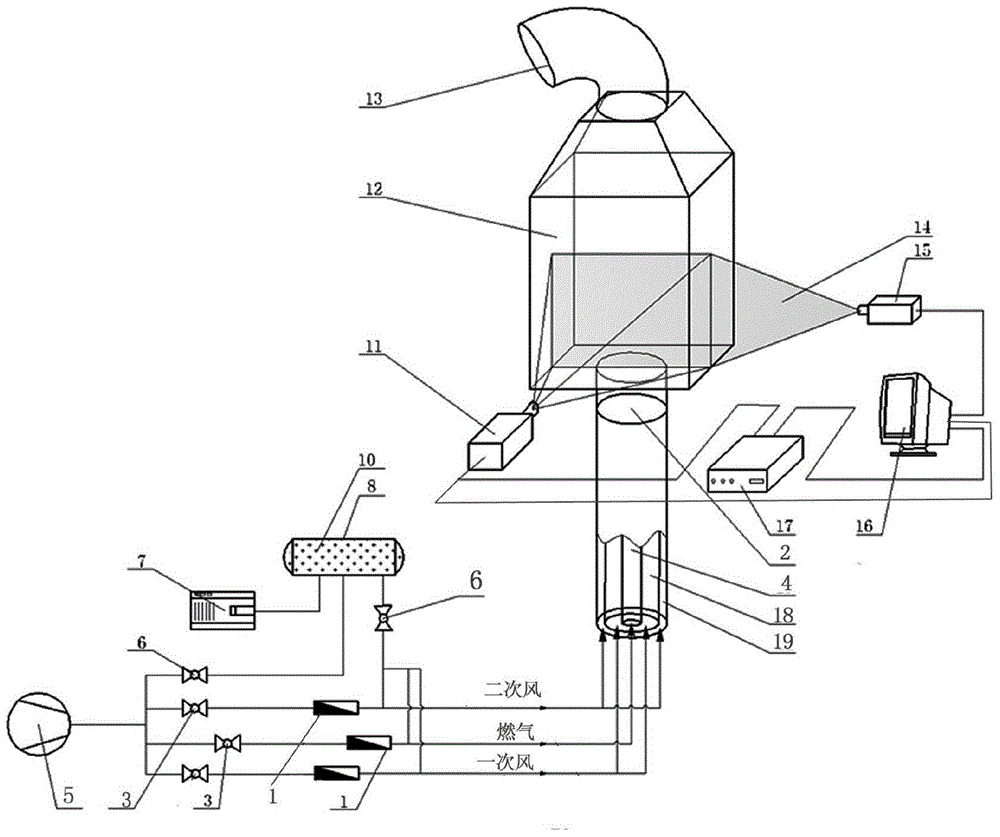
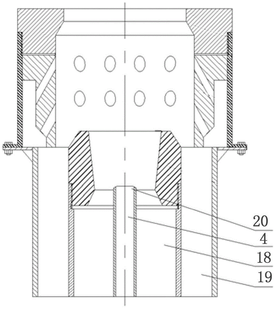
[0046] see figure 2 , the device in this embodiment is basically the same as that in Embodiment 1, the only difference is that the secondary air pipe 19 and the primary air pipe 18 are used to replace the air pipe in Embodiment 1, and the discharge port of the buffer tank 8 is connected to the primary air pipe. Tube 18 is connected. In this test device, the burner structure is shown in image 3 , the secondary air pipe 19, the primary air pipe 18 and the gas pipe 4 are coaxially nested and designed coaxially with the gas spray gun 20, and the dimensions are respectively Φ 160 × 7.5 mm, Φ 100 × 7.5 mm, Φ 20 × 3mm. The dimensions of the cuboid part of the transparent combustion chamber are 500 × 500 × 790 mm.


PUM


Abstract

The invention relates to a testing device for measuring a cold-state flow field in a gas burner based on a PIV (particle image velocimetry) technique. The testing device comprises a heating furnace cold-state model, a gas path system, a trace particle scattering device and a PIV testing system. By integrating the heating furnace cold-state model, the gas path system, the trace particle scattering device and a PIV imaging and image processor, the testing device for measuring the cold-stage flow field in the gas burner based on the PIV technique avoids disturbance of a traditional contact-type measurement means to actual flow, also avoids the defect that the flow field cannot be measured in a large scale through a single-point measurement method, and can test movement characteristics of gas flow generated by the gas burner in a combustion chamber quickly and accurately. The image processor conducts self-correlation and time averaging processing on smog trace particle original images measured through PIV to obtain an average speed vector diagram, and accordingly, the distribution of the flow field is analyzed.

Description

technical field [0001] The invention relates to a test device based on PIV technology, in particular to a test device for measuring the cold flow field in a gas burner furnace based on PIV technology. Background technique [0002] PIV (Particle Image Velocimetry) technology is a non-contact flow field measurement technology, which obtains flow velocity information through cross-correlation analysis of flow field images, and can perform high-resolution and high-precision measurement of two-dimensional flow fields in the plane and three-dimensional flow fields in space. test. As a basic means of studying various complex flow fields, PIV technology has been widely used in the flow field measurement of hydrodynamic experiments and aerodynamic experiments. From steady to unsteady, low-speed to high-speed, single-phase to multi-phase, the relevant quantitative information of the entire plane is recorded at the same time, so as to obtain the instantaneous velocity field, pulsating...

Claims


Application Information

Patent Timeline
IPC IPC(8): G01M9/00
Inventor 谭金龙刘波王元华张开伦刘小春刘勇蒋良雄吴晓磊
Owner CHINA PETROLEUM & CHEM CORP
Learn More