
Experimental device and testing method for rapidly determining corrosion rate of reinforcing steel bars

A technology for rapid determination of corrosion of steel bars, applied in measuring devices, weather resistance/light resistance/corrosion resistance, instruments, etc. It can solve the problems of low test accuracy, crevice corrosion of steel bar samples, and poor validity of experimental test results. Accurate, proven effectiveness

Active Publication Date: 2015-04-29
NANJING IRON & STEEL CO LTD
View PDF6 Cites 20 Cited by
  • Summary
  • Abstract
  • Description
  • Claims
  • Application Information

AI Technical Summary

Problems solved by technology

[0005] In view of the defects in the above-mentioned prior art, the purpose of this invention is to propose a method for quickly measuring the corrosion rate of steel bars, to solve the problem of crevice corrosion easily occurring in steel bar samples when measuring the corrosion rate of low-alloy steel bars, and the accuracy of experimental testing is low. The problem with poor result validity

Method used


Image

  • Experimental device and testing method for rapidly determining corrosion rate of reinforcing steel bars
  • Experimental device and testing method for rapidly determining corrosion rate of reinforcing steel bars
  • Experimental device and testing method for rapidly determining corrosion rate of reinforcing steel bars

Examples


Embodiment 1

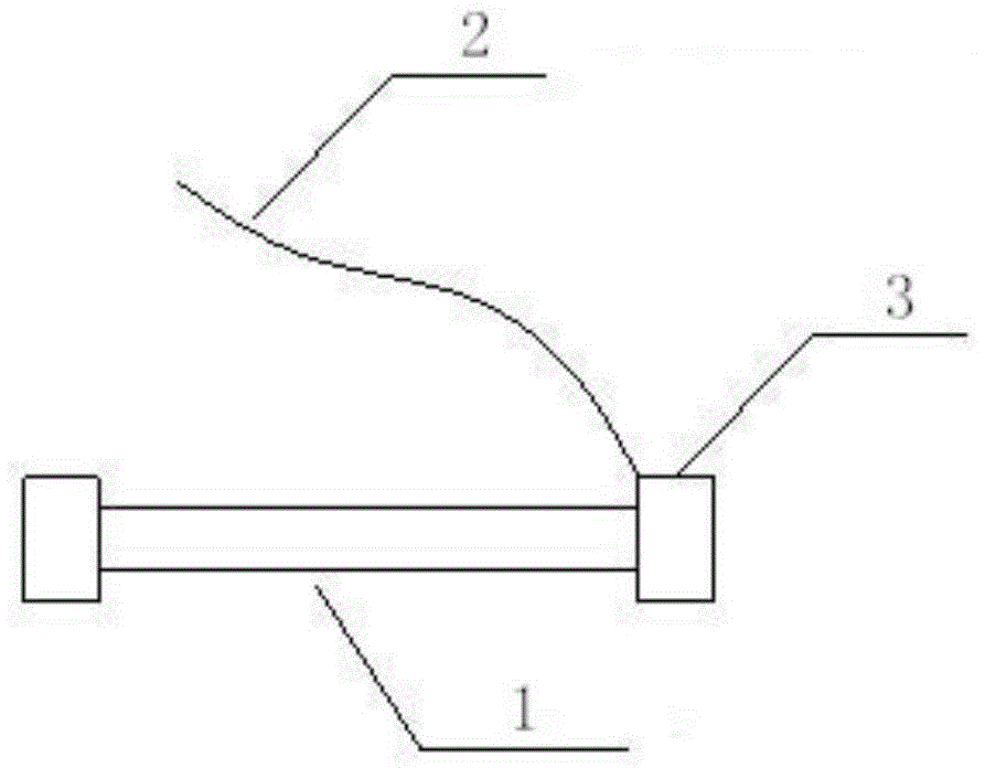
[0023] First prepare the sample: according to figure 1 To make the sample, select 1# and 2# rod-shaped steel bar samples with φ16×125mm to remove the surface oxide scale. One end of the steel bar 1 is welded with the wire 2, and the surface of the wire is covered with an insulating protective sheath. The end of the steel bar and the The wires are sealed with epoxy resin 3, while the exposed length of the steel bars is 100mm.

[0024] Next, prepare the solution: use deionized water with a conductivity of less than 2 μs / cm to prepare the solution, and prepare the anode concrete simulation liquid and the cathode concrete simulation liquid. The anode concrete simulation liquid is a hydroxide containing 0-15% sodium chloride Calcium solution, the cathode concrete simulation fluid is a saturated calcium hydroxide solution.

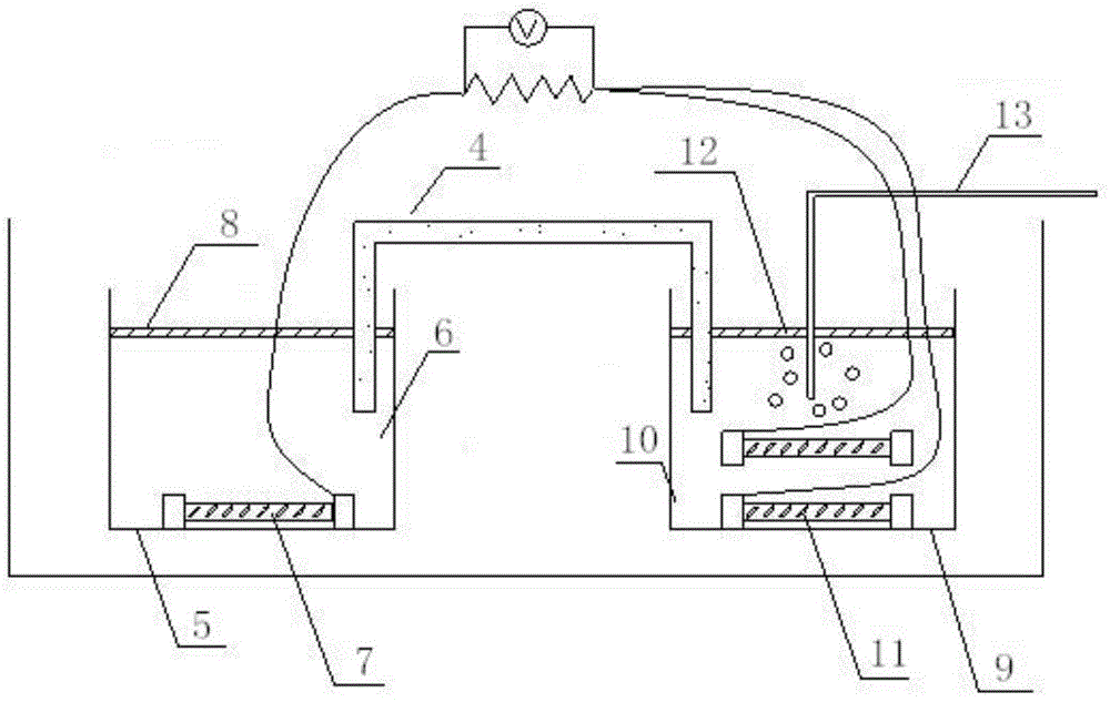
[0025] Set up the device and mount the specimen: follow figure 2 Build the experimental device, including the anode test mechanism, cathode test mechanism, c...

Embodiment 2

[0029] First prepare the sample: according to figure 1 To make the sample, select 1# and 2# bar-shaped steel bar samples with φ11.3×125mm without removing the surface oxide scale. One end of the steel bar 1 is welded with the wire 2, and the surface of the wire is covered with an insulating protective sheath. The ends and wires are sealed with epoxy resin 3, and the exposed length of the steel bar is 60mm.

[0030] Next, prepare the solution: use deionized water with a conductivity of less than 2 μs / cm to prepare the solution, and prepare the anode concrete simulation liquid and the cathode concrete simulation liquid. The anode concrete simulation liquid is a hydroxide containing 0-15% sodium chloride Calcium solution, the cathode concrete simulation fluid is a saturated calcium hydroxide solution.

[0031] Set up the device and mount the specimen: follow figure 2 Build the experimental device, including the anode test mechanism, cathode test mechanism, current test device ...


PUM

PropertyMeasurementUnit
Lengthaaaaaaaaaa

Abstract

The invention discloses an experimental device and a testing method for rapidly determining the corrosion rate of reinforcing steel bars. The method comprises the following steps: I, preparing a test sample; II, preparing a solution; III, establishing a device; IV, installing the test sample; and V, testing the test sample. The invention provides an experimental device and a testing method for rapidly determining corrosion rate of reinforcing steel bars by adopting a macro battery, no gap corrosion of the test sample in testing can be guaranteed, the experimental testing accuracy is high, the consistent testing results can be shown by performing electrochemical linear polarization testing to the reinforcing steel bars and service environment sample feeding testing to reinforcing steel concrete test samples, and the efficiency of the testing method can be effectively proven.

Description

technical field [0001] The invention relates to a method for measuring the corrosion rate of steel bars, in particular to a method for quickly measuring the corrosion rate of steel bars for concrete, and belongs to the technical field of corrosion performance detection methods for metal materials. Background technique [0002] As a building material, steel bars have been widely used in concrete structures. Reinforced concrete structures often fail early before reaching the service life, because the steel bars are corroded, and the accumulated corrosion products cause the concrete to generate internal stress and crack. Therefore, it is very important to evaluate the corrosion performance of steel bars. Corrosion rate is one of the important parameters to characterize the corrosion performance of steel bars. The weight loss method is usually used to measure the corrosion rate, but when the interaction between the sample and the environmental medium is a passivation system, th...

Claims


Application Information

Patent Timeline
IPC IPC(8): G01N17/02
Inventor 蔡佳兴范益张万灵
Owner NANJING IRON & STEEL CO LTD
Learn More