Line voltage detection circuit for switching power supply

A detection circuit, switching power supply technology, applied in the direction of measuring current/voltage, measuring device, measuring electrical variables, etc., can solve the problem of reducing the batch consistency of constant current output, the compensation effect of the compensation circuit deviating from the design value, and the switching power supply line voltage detection circuit Can not meet the needs of users and other problems, to achieve the effect of improving accuracy and batch consistency

Active Publication Date: 2015-04-29
SHANGHAI BEILING
View PDF24 Cites 2 Cited by
  • Summary
  • Abstract
  • Description
  • Claims
  • Application Information

AI Technical Summary

Problems solved by technology

[0003] However, in the current line voltage detection circuit of the existing switching power supply, the ratio of the detected output current value to the line voltage input is set as a fixed value inside the control chip, and the fixed value cannot adapt to the parameter change of the system circuit board, so that the compensation The compensation effect of the circuit deviates from the design value. In addition, the fixed value set inside the chip is affected by the production process and has a large degree of dispersion, thereby reducing the batch consistency of the constant current output.
Therefore, the existing switching power supply line voltage detection circuit has been increasingly unable to meet the needs of users

Method used


Image

  • Line voltage detection circuit for switching power supply

Examples


Embodiment Construction

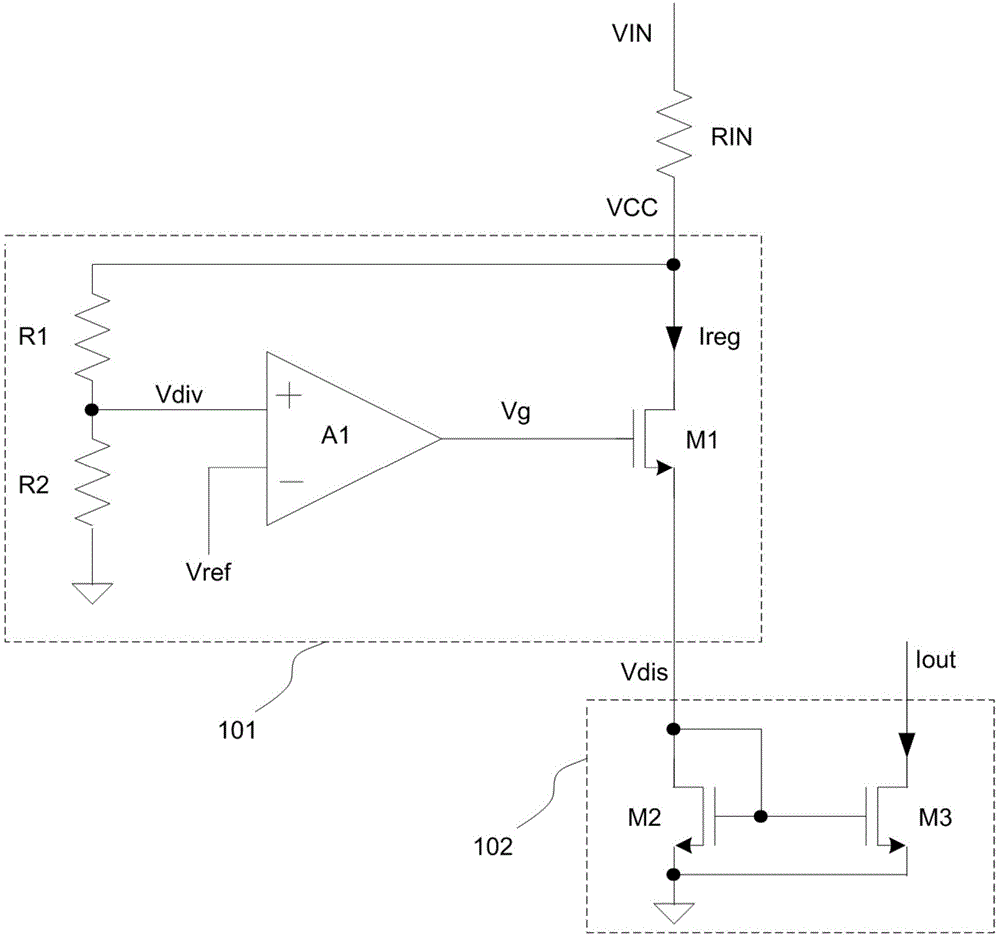
[0018] The line voltage detection circuit of the switching power supply of the present invention will be specifically described below in conjunction with the accompanying drawings. figure 1 It is a circuit diagram of the line voltage detection circuit of the switching power supply of the present invention. The line voltage detection circuit of the switching power supply of the present invention is used for inputting the line voltage VIN according to the line voltage input terminal, and outputting a proportional detection current Iout to the subsequent compensation circuit.

[0019] As shown in the figure, the voltage regulation module 101 has a first output terminal for outputting a first regulation voltage VCC, and a second output terminal for outputting a regulation current Ireg, and the second output terminal also outputs a discharge voltage Vdis. A first voltage dividing resistor R1 and a second voltage dividing resistor R2 are connected in series between the first output ...


PUM


Abstract

A line voltage detection circuit for a switching power supply comprises a line voltage input end used for inputting a line voltage, an input resistor, a voltage regulator module and a current sampling module, wherein the input resistor, the voltage regulator module and the current sampling module are connected in sequence; one end of the input resistor is connected with the line voltage input end, and the other end of the input resistor is connected with the voltage regulator module; the voltage regulator module comprises a first output end used for outputting a regulating voltage, a second output end used for outputting a regulating current, and an input end used for outputting a reference voltage, and the voltage regulator module controls the regulating voltage and outputs the regulating current to the current sampling module; an input end of the current sampling module is connected with the second output end of the voltage regulator module and used for receiving the regulating voltage, and an output end of the voltage regulator module is used for outputting a detection current proportional to the regulating current. By means of the line voltage detection circuit for the switching power supply, the ratio of a detection output value and a line voltage input value can be set according to a resistance value inputted to the resistor.

Description

technical field [0001] The invention relates to a line voltage detection circuit of a switching power supply. Background technique [0002] The line voltage of the switching power supply, that is, the input voltage of the switching power supply circuit. When the switching power supply circuit works in the constant current output mode, due to the inherent defect of the closed-loop constant current control method, the output current amplitude is affected by the input voltage, that is, the line voltage amplitude, and the degree of this influence is also related to the system circuit board parameters. Internally, through an additional compensation circuit, the amplitude of the output current will be compensated according to the amplitude of the detected line voltage, so as to achieve the purpose of constant current output. Therefore, a line voltage detection circuit of a switching power supply is needed, which is used to output a detection current related to the line voltage an...

Claims


Application Information

Patent Timeline
Patent Type & Authority Applications(China)
IPC IPC(8): G01R19/00
Inventor 李淼
Owner SHANGHAI BEILING
Why Eureka
Try Eureka