Optical coupling lens

An optical coupling and lens technology, which is applied in the field of optical coupling lenses, can solve problems such as irregular deformation of pins, affecting the alignment of optical fibers and optical convergence parts, and low manufacturing yield of optical coupling lenses, so as to avoid irregular deformation and improve The effect of manufacturing yield

Inactive Publication Date: 2015-04-29
武汉冠宇世纪科技技术有限公司
View PDF3 Cites 4 Cited by
  • Summary
  • Abstract
  • Description
  • Claims
  • Application Information

AI Technical Summary

Problems solved by technology

However, when the optical coupling lens is injection-molded, the process of injecting the material into the mold will generate exhaust gas called gas, which concentrates at the end face of the pin to be formed, resulting in irregular deformation of the molded pin , for example, the side of the formed pin expands or shrinks, so that it cannot be matched with the corresponding socket and inserted into the corresponding socket smoothly, and finally affects the alignment between the optical fiber and the optical convergence part
It can be seen that the manufacturing yield of optical coupling lenses with traditional pins is low

Method used


Image

  • Optical coupling lens
  • Optical coupling lens
  • Optical coupling lens

Examples


Embodiment Construction

[0014] The embodiments of the present invention will be further described in detail below in conjunction with the accompanying drawings.

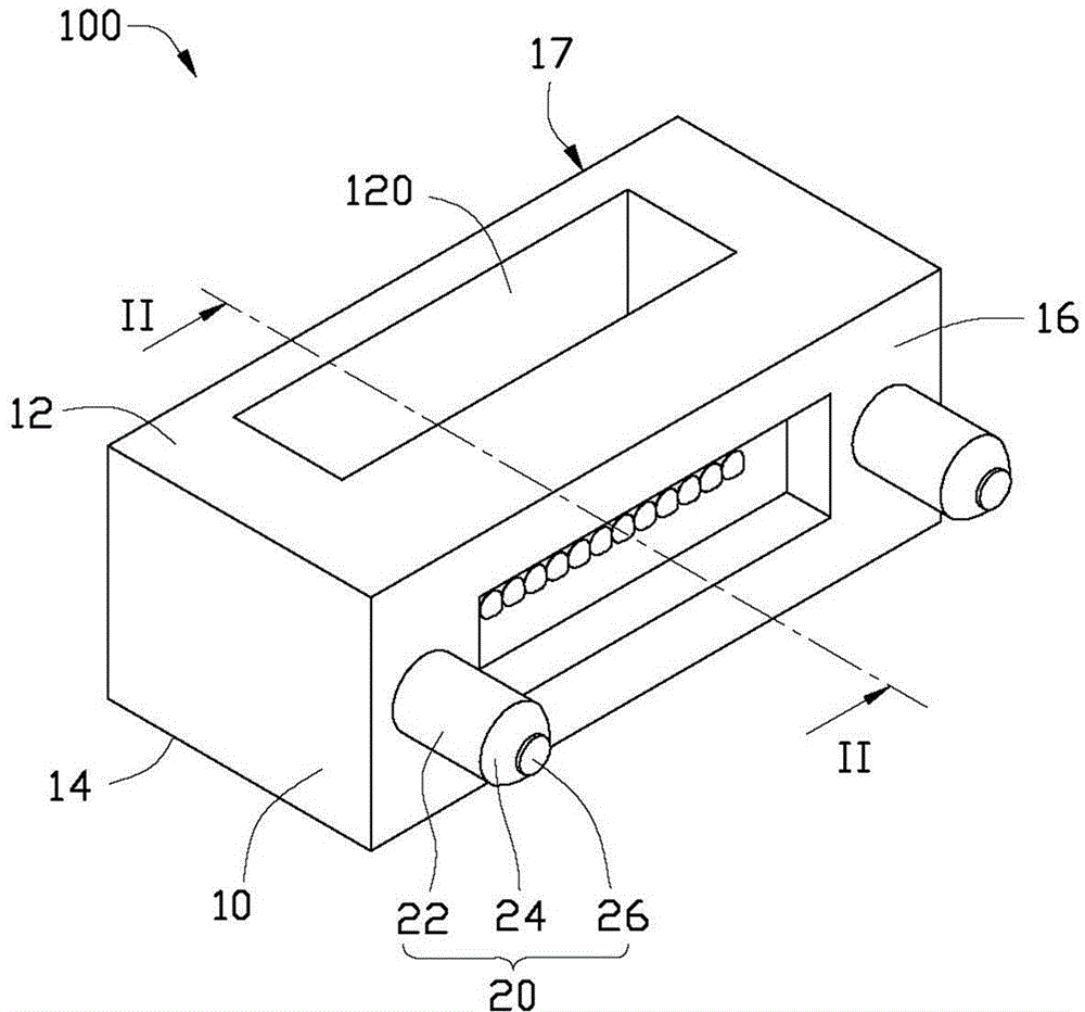
[0015] see figure 1 , is the optical coupling lens 100 provided in the first embodiment of the present invention. The optical coupling lens 100 includes a coupling body 10 and two pins 20 .

[0016] The coupling body 10 is substantially in the shape of a cuboid, and includes an upper surface 12 , a lower surface 14 , a front surface 16 , a rear surface 17 , a plurality of first converging portions 18 and a plurality of second converging portions 19 . The upper surface 12 and the lower surface 14 are located on opposite sides of the coupling body 10 , and the upper surface 12 is parallel to the lower surface 14 . The front surface 16 and the rear surface 17 are located on opposite sides of the coupling body 10 , and the front surface 16 is parallel to the rear surface 17 . The front surface 16 is vertically connected to the upper surface ...


PUM


Abstract

The invention relates to an optical coupling lens. The optical coupling lens comprises a coupling body and two plug pins, wherein the coupling body comprises a front surface, a back surface, a first optical surface, a second optical surface, a reflecting surface, a plurality of first converging parts and a plurality of second converging parts, wherein the front surface and the back surface are parallel to each other and are back to each other; the first optical surface is sunken from the front surface towards the back surface; the second optical surface is perpendicular to the first optical surface; the reflecting surface is inclined relative to the first optical surface and the second optical surface; the first converging parts and the second converging parts are respectively positioned on the first optical surface and the second optical surface. The first converging parts are positioned between the two plug pins and are in one-to-one correspondence with the second converging parts. Each plug pin comprises a cylindrical body part, a boss part which extends from the end surface of the body part, and a buffer part. The boss part is of a bowl-shaped structure and comprises a top surface which is far away from the body part; the diameter of the boss part is gradually reduced in the direction from the end surface to the top surface. The buffer part is arranged on the top surface so as to buffer the methane gas which is concentrated at the top surface when the optical coupling lens is formed.

Description

technical field [0001] The invention relates to the field of Universal Serial Bus (USB), in particular to an optical coupling lens. Background technique [0002] At present, the use of optical signals to transmit data is gradually applied to the USB field of personal computers, and the specific form is embodied in the use of optical fiber coupling connectors. Generally, a fiber coupling connector includes an optical coupling lens, a receiving portion, and a plurality of optical fibers. The optical coupling lens is provided with two pins and a plurality of optical converging parts between the two pins. Two sockets corresponding to the two pins are arranged on the receiving part. The plurality of optical fibers are accommodated in the accommodation portion. In use, the two pins are plugged into the corresponding sockets so that the receiving portion is connected to the optical coupling lens, and the plurality of optical fibers are aligned with the plurality of optical conve...

Claims


Application Information

Patent Timeline
Patent Type & Authority Applications(China)
IPC IPC(8): G02B6/42
CPCG02B6/4204
Inventor 林奕村
Owner 武汉冠宇世纪科技技术有限公司
Why Eureka
Try Eureka