Design method of free-form surface imaging system

A technology of imaging system and design method, applied in the direction of optical components, optics, instruments, etc., can solve the problems of slow optimization process, limited application range of the method, easy to fall into local optimum, etc. The method is simple and the number of fields of view is not limited , the effect of broad application space

Active Publication Date: 2015-04-29
TSINGHUA UNIV +1
View PDF6 Cites 14 Cited by
  • Summary
  • Abstract
  • Description
  • Claims
  • Application Information

AI Technical Summary

Problems solved by technology

For free-form surfaces with many variables, the optimization process can be slow and can easily get stuck in a local optimum; in addition, since different systems have different aberration characteristics due to their different structures

Method used


Image

  • Design method of free-form surface imaging system
  • Design method of free-form surface imaging system
  • Design method of free-form surface imaging system

Examples


Embodiment Construction

[0022] The technical solution of the present invention will be further described in detail below according to the drawings in the description and in combination with specific embodiments.

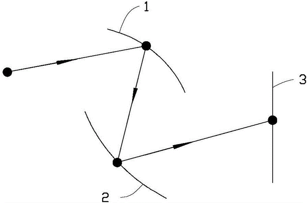
[0023] see figure 1 and figure 2 The free-form surface imaging system provided by the present invention includes a first curved surface 1 and a second curved surface 2 that are adjacent and spaced apart. The light exiting from the pupil of an object or diaphragm is incident on the first curved surface 1 and passes through the first curved surface 1 and the second curved surface in sequence. After the second curved surface 2 is refracted or reflected, an image is formed on an image plane 3 . The two curved surfaces in the free-form surface imaging system can be added behind other optical systems, such as for correcting system aberrations or realizing specific image plane transformation, or can form an optical system independently.

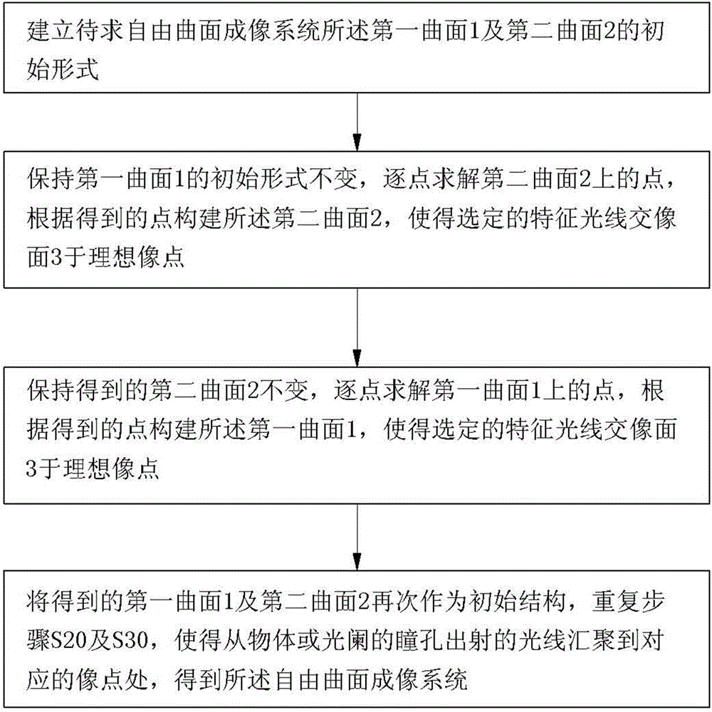
[0024] The design method of the freeform surface imaging...


PUM


Abstract

A design method of freeform imaging system is provided. An initial freeform imaging system is provided, the initial freeform image system comprising a first initial surface and a second initial surface spaced from each other. A second surface is constructed by calculating a plurality of second data points of the second surface through a plurality of feature rays based on the given object-image relationship. A first surface is constructed by calculating a plurality of first data points of the first surface based on the given object-image relationship and Fermat's principle, wherein the second surface is fixed. The first surface and the second surface substitute for the first initial surface and second initial surface respectively, and repeating steps list above, wherein the plurality of feature rays are intersecting the image plane at the plurality of ideal image points.

Description

technical field [0001] The invention relates to the field of optical design, in particular to a design method of a free-form surface imaging system based on point-by-point solution and iteration of a curved surface. Background technique [0002] Free-form surfaces refer to non-traditional surfaces that cannot be represented by spherical or aspherical coefficients. They are usually non-rotational symmetric, flexible in structure, and have many variables, which provide more degrees of freedom for optical design and can greatly reduce the aberration of the optical system. , to reduce the volume, weight and number of lenses of the system. In recent decades, freeform surfaces have been successfully used in non-imaging fields, especially in lighting. For the field of modern imaging, the field of view and aperture of the optical system are larger, which puts forward higher requirements for image quality, volume, and weight. At the same time, the system structure is more complicate...

Claims


Application Information

Patent Timeline
IPC IPC(8): G02B27/00
CPCG02B27/0012
Inventor 杨通朱钧金国藩范守善
Owner TSINGHUA UNIV
Why Eureka
Try Eureka