Energy-saving power supply control system and method

A technology of power control and power supply, applied in general control system, control/regulation system, electrical program control, etc., can solve the problem of increasing standby power consumption and achieve the effect of reducing power consumption

Active Publication Date: 2015-04-29
GREE ELECTRIC APPLIANCES INC
View PDF7 Cites 1 Cited by
  • Summary
  • Abstract
  • Description
  • Claims
  • Application Information

AI Technical Summary

Problems solved by technology

When the motherboard is in standby, all circuits are powered on, and many infrequently used power circuits, such as buzzer circuits and USB circuits, are only used in rare cases and are always powered on, which increases standby power consumption

Method used


Image

  • Energy-saving power supply control system and method
  • Energy-saving power supply control system and method
  • Energy-saving power supply control system and method

Examples


Embodiment 1

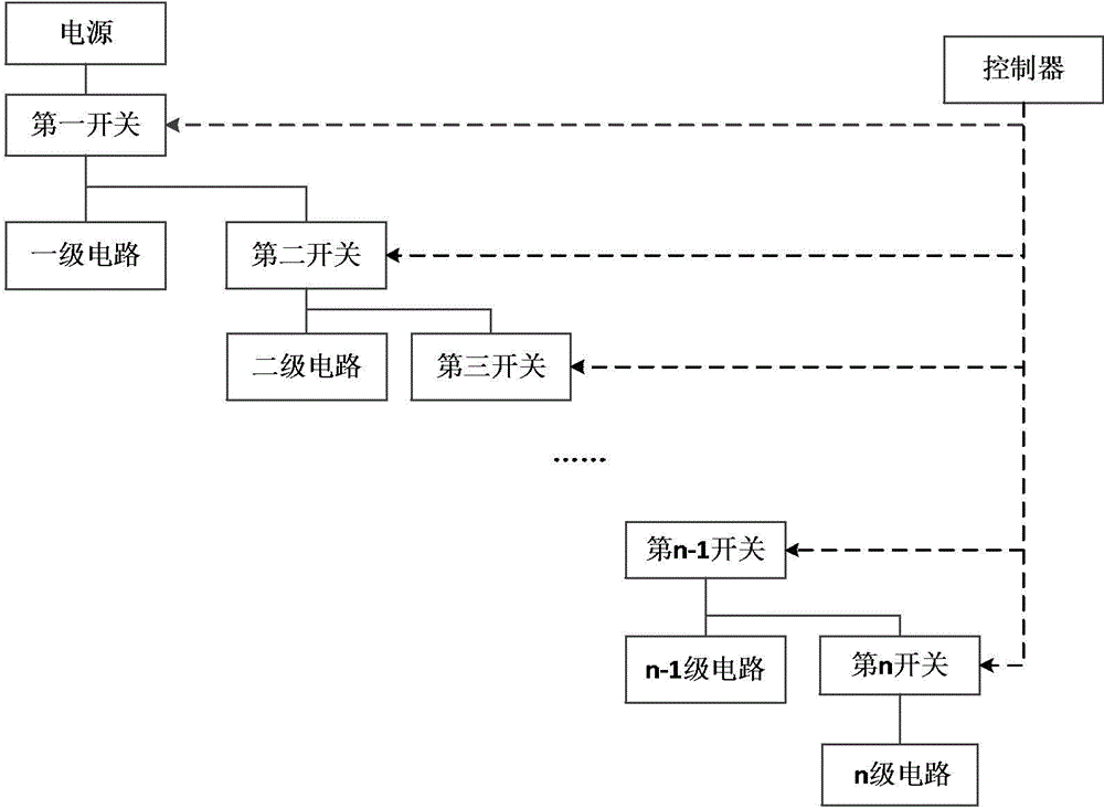
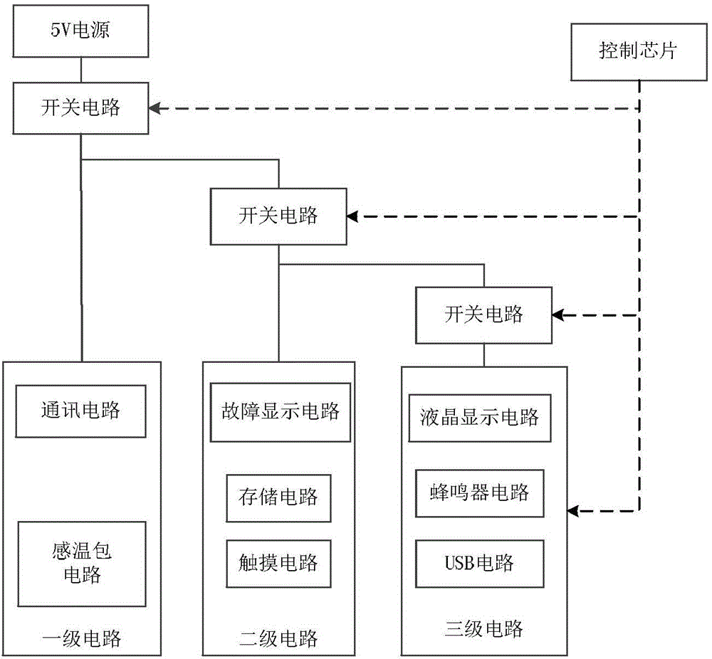
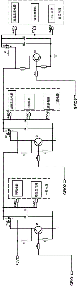
[0025] figure 1 It is a functional block diagram of an energy-saving power supply control system according to Embodiment 1 of the present invention; figure 2 It is a structural block diagram when the energy-saving power supply control system of Embodiment 1 of the present invention is used to control the main board of the air conditioner controller. exist figure 1 and figure 2 In , the solid line represents the electrical connection, and the dotted line with the arrow represents the direction of signal transmission, that is, the same controller controls the on-off of all switches. It should be noted, figure 1 In , the circuit in the middle is represented by an ellipsis, and the circuit at the lowest level is represented by n.

[0026] Such as figure 1 As shown, the energy-saving power supply control system according to Embodiment 1 of the present invention is used to control the power supply to supply power to multiple power consumption circuits. The power supply contro...

Embodiment 2

[0034] Figure 4 It is a functional block diagram of an energy-saving power supply control system according to Embodiment 2 of the present invention; Figure 5 It is a structural block diagram when the energy-saving power supply control system of the second embodiment of the present invention is used to control the main board of the air conditioner controller. Similarly, in Figure 4 and Figure 5 In , the solid line represents the electrical connection, and the dotted line with the arrow represents the direction of signal transmission, that is, the same controller controls the on-off of all switches. Similarly, Figure 4 In , the circuit in the middle is represented by an ellipsis, and the circuit at the lowest level is represented by n. Wherein, the first switch and the second switch are only used for distinction as a description. First-level circuits, second-level circuits... n-level circuits represent circuits with different frequencies of use, and are arranged in des...

Embodiment 3

[0039] Figure 6 It is a structural block diagram when the energy-saving power supply control system of Embodiment 3 of the present invention is used to control the main board of the air conditioner controller.

[0040] Such as Figure 6 As shown, the third embodiment adopts the combination of series and parallel connection between the switch circuits, wherein the switch circuits of the secondary circuit and the tertiary circuit are first connected in parallel, and then they are connected in series with the switch circuits of the primary circuit. The secondary circuit and the tertiary circuit are independent of each other, but their conduction requires the conduction of the switch circuit of the primary circuit as a prerequisite. In this embodiment, multiple switches are connected in parallel first and then in series, which can also realize that the third-level circuit and the second-level circuit with lower frequency are only turned on when they are working, so as to reduce ...


PUM


Abstract

The invention discloses an energy-saving power supply control system and method. The power supply control system controls a power supply to supply power for multiple electricity consumption circuits and comprises a controller and multiple switches, wherein the controller controls the on-off of the multiple switches; the multiple electricity consumption circuits are classified from high operating frequency to low operating frequency; each circuit comprises one or more electricity consumption circuits and one switch connected in series. The invention further discloses a corresponding energy-saving power supply control method. The classified or independent power supply for the electricity consumption circuits is realized by increasing the number of the switches, and rarely used circuits are only powered on when need to work, so that the energy consumption, especially the stand-by power consumption is reduced.

Description

technical field [0001] The present invention relates to the technical field of power supply control, in particular, to an energy-saving power supply control system and control method, which classifies the power consumption circuits according to the frequency of use, and adopts hierarchical control or independent control methods to control the on-off of each stage of the circuit, so that Infrequently used circuits are only energized when in use, saving energy. Background technique [0002] Energy saving and emission reduction is the general trend of today's society, and it is also a design requirement for almost all electrical products. Almost all electrical appliances, including air conditioners, are automatically controlled, and the controller controls the operation of the host machine according to the settings. The inventors found that in the prior art, the power consumption of the whole commercial air conditioner is relatively large, especially the power consumption of t...

Claims


Application Information

Patent Timeline
Patent Type & Authority Applications(China)
IPC IPC(8): G05B19/418
CPCY02P90/02G05B19/418G05B2219/00
Inventor 贺小林苏玉海金国华肖焕明杨都吴兴初玉维友
Owner GREE ELECTRIC APPLIANCES INC
Why Eureka
Try Eureka