Eureka AIR delivers breakthrough ideas for toughest innovation challenges, trusted by R&D personnel around the world.

Method for calculating direct-current transmission line electric field intensity and radio interference

A technology for direct current transmission lines and radio interference, which is applied in the field of electric power and can solve the problems such as the inability to directly set the mirror charge of the wire and the uneven terrain of the vertical section of the wire.

Active Publication Date: 2015-04-29
YUNNAN POWER GRID CO LTD ELECTRIC POWER RES INST
View PDF4 Cites 8 Cited by
  • Summary
  • Abstract
  • Description
  • Claims
  • Application Information

AI Technical Summary

Problems solved by technology

However, the vertical section of the actual transmission line conductor is often in uneven terrain
The calculation method based on the above literature cannot be directly used in the calculation of electric field strength and radio interference of DC lines under complex conductor vertical section terrain
[0004] The literature "Analysis of Electromagnetic Environment Characteristics of High-Voltage AC Transmission Lines under Complex Terrain Conditions" and "Power Frequency Electric Field of Ultra-High-Voltage Transmission Lines under Complex Terrain Conditions" carried out the analysis of electromagnetic environment characteristics of high-voltage AC transmission lines under complex terrain conditions based on the optimized simulated charge method. But the method is to empirically set the position of the simulated charge
Documents "A New Method for Power Frequency Electric Field Calculation of Transmission Conductors Considering Meteorological Conditions" and "Three-Dimensional Power Frequency Electromagnetic Field Calculation of Cross-Span Transmission Conductors" use genetic algorithms to optimize the sag of transmission conductors and UHV insulator grading rings, respectively. The traditional method is only for flat wire sections, using the image charge equivalent to the induced charge on the ground surface, and for the situation where the wire section of the transmission line has ups and downs, it is impossible to directly set the wire image charge

Method used


Image

  • Method for calculating direct-current transmission line electric field intensity and radio interference
  • Method for calculating direct-current transmission line electric field intensity and radio interference
  • Method for calculating direct-current transmission line electric field intensity and radio interference

Examples


Embodiment Construction

[0077] The technical solutions of the present invention will be clearly and completely described below in conjunction with the accompanying drawings and embodiments.

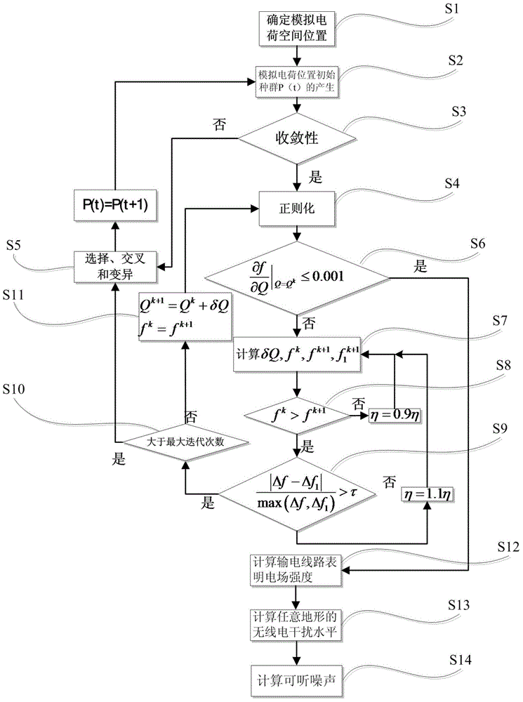
[0078] Such as figure 1 As shown, a method for calculating the electric field strength and radio interference of a DC transmission line, the specific steps are as follows:

[0079] S1: Determine the spatial position of the simulated charge

[0080] According to the principle of the simulated charge method, in the value range of the simulated charge space position in formula (1), the simulated charge coordinates of the conductor and the lightning conductor and the center of the subconductor where they are located are compared to obtain the value range of the simulated charge of the conductor and the lightning conductor is the corresponding diameter; the simulated charge in formula (1) must be in the non-computing field wires, lightning conductors, or located below the earth’s surface, so the position of the simu...


PUM


Abstract

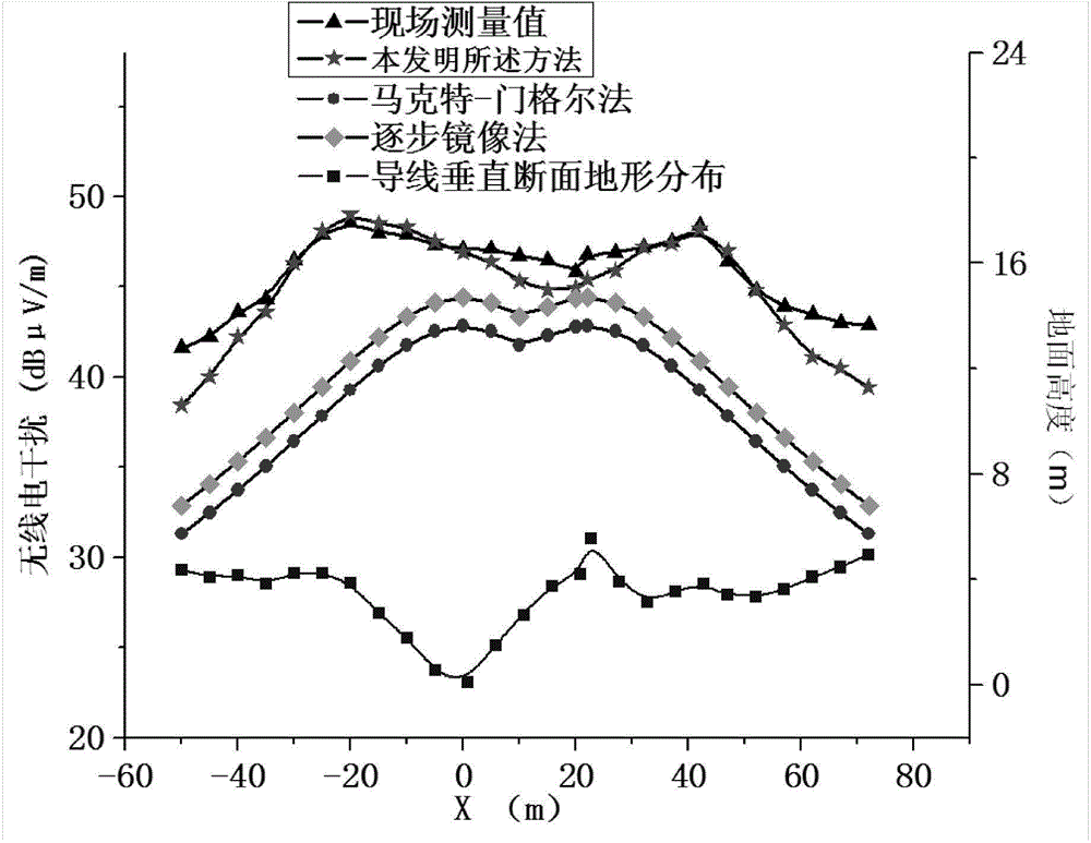
The invention discloses a method for calculating direct-current transmission line electric field intensity and radio interference. The method solves the problems that in the prior art and a traditional method, a transmission line lead section has waved relief, so that lead mirror image charge cannot be directly set, and ill-posed problems of an original equation can be solved when a direct-current transmission line adopts linear equations such as a Gauss-Newton method. Compared with a traditional partial discharge method, experimental efficiency is improved, and the method has practicability and feasibility through experimental verification.

Description

technical field [0001] The invention belongs to the field of electric power technology, and in particular relates to a method for calculating electric field strength and radio interference of direct current transmission lines in the field of high voltage and extra high voltage. Background technique [0002] High-voltage or UHV DC transmission technology is widely used in the transmission project of the main channel of west-to-east power transmission. However, with the increase of voltage level, its electromagnetic environment impact has attracted more and more public attention and key considerations in line design. The synthetic electric field, ion current, DC magnetic field under the DC line, as well as the radio interference and audible noise generated by the corona will have a certain impact on the production and life of Juming along the line. Studies have shown that the level of radio interference is one of the important electromagnetic environment indicators in the EIA ...

Claims


Application Information

Patent Timeline
IPC IPC(8): G06F17/50G06N3/12G06Q50/06
CPCY02E60/00
Inventor 沈鑫闫永梅曹敏张林山
Owner YUNNAN POWER GRID CO LTD ELECTRIC POWER RES INST
Why Eureka
Eureka Blog
Learn More