Optical system imaging recovering method based on light intensity transmission matrix

A light intensity transmission matrix and optical system technology, which is applied in the field of optical system imaging restoration and imaging quality improvement, can solve the problems of missing high-frequency components of restored objects, large restoration errors, etc., and achieve the effect of small errors and high restoration accuracy

Active Publication Date: 2015-04-29
HARBIN INST OF TECH
View PDF3 Cites 3 Cited by
  • Summary
  • Abstract
  • Description
  • Claims
  • Application Information

AI Technical Summary

Problems solved by technology

Therefore, the frequency domain restoration method can only restore the object spectrum within the OTF cut-off frequency, resulting in the loss of high-frequency components of the restored object and large restoration errors.

Method used


Image

  • Optical system imaging recovering method based on light intensity transmission matrix
  • Optical system imaging recovering method based on light intensity transmission matrix
  • Optical system imaging recovering method based on light intensity transmission matrix

Examples


example 1

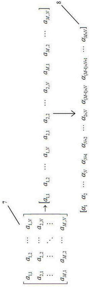
[0077] In order to fully illustrate the solution method of the two-dimensional light intensity transmission matrix of the present invention, Image 6 An example of a two-dimensional image matrix composed of elements in 5 rows and 5 columns and a one-dimensional image vector after one-dimensionalization is given. Figure 7 given the basis Figure 5 The two-dimensional unknown original matrix with 5 rows and five columns of elements and the one-dimensionalized unknown original vector established by the two-dimensional image matrix are as large as the two-dimensional image matrix. During the solution process, the two-dimensional unknown original matrix All elements in the 1D unknown primitive vector are unknown. Figure 8 An example of PSF matrix composed of 3 rows and 3 columns is given, and the optical system is a linear space invariant system. Each element in the two-dimensional unknown original matrix will form diffuse spots on the image plane through the action of the PSF ...

example 2

[0079] In order to further explain the solution method of the two-dimensional light intensity transmission matrix and the calculation of the restoration error in the imaging restoration technology, Figure 14 (a) Given the known two-dimensional primitive for the pattern of the letter F with elements in 7 rows and 7 columns, Figure 14 (b) The two-dimensional original matrix of the letter F pattern is given. In the restoration process, the original matrix can be considered as unknown. In the calculation process of the restoration error after restoration, the original matrix is ​​already known Known. Figure 15 The PSF matrix data of an optical system is given, which is a linear space-invariant system. Figure 16 (a) gives the image of the letter F object, Figure 16 (b) The two-dimensional image matrix is ​​given. It can be seen that due to the poor imaging quality of the optical system, the image is very blurred, and the two-dimensional image matrix data is very different fr...

example 3

[0081] In order to verify the restoration effect of this restoration method on the image matrix with a large amount of data, Figure 21 Given a known primitive with 400 rows and 400 columns of elements, Figure 22 The PSF matrix of the optical system is given (the optical system is a linear space invariant system), Figure 23 gives Figure 21 The original object shown is the image formed by the optical system. It can be seen that due to the poor imaging quality of the optical system, the original image is very blurred. First put Figure 23 If the two-dimensional matrix of the image in is one-dimensionalized, a one-dimensional image vector containing 160,000 elements can be obtained, and then a two-dimensional light intensity transmission matrix can be constructed according to formula (3) and the method described in Example 1, and 160,000 rows, 160,000 The two-dimensional light intensity transmission matrix of the column, because the number of elements of the matrix is ​​to...


PUM


Abstract

The invention relates to an optical system imaging recovering method based on a light intensity transmission matrix. The optical system imaging recovering method includes the steps that S1, each row of elements in a two-dimensional image matrix are sequentially connected end to end and arrayed to be one-dimensional image vectors; S2, according to a PSF matrix of an optical system and the one-dimensional image vectors, the two-dimensional light intensity transmission matrix of the optical system is solved, and inversion mathematical calculation is carried out on the two-dimensional light intensity transmission matrix to obtain a two-dimensional light intensity transmission inverse matrix; S3, the one-dimensional image vectors are multiplied with the two-dimensional light intensity transmission inverse matrix to obtain one-dimensional recovering object vectors, and two-dimensional processing is carried out on the one-dimensional recovering object vectors to obtain a two-dimensional recovering object matrix. Imaging is recovered through matrix operation, the ill-conditioned problem of a deconvolution method and the high frequency missing problem of a frequency domain recovering method in the previous imaging recovering technology are avoided, the error between the recovering object matrix and an original object matrix is very small, and therefore the recovering accuracy is high.

Description

technical field [0001] The invention belongs to the technical field of optical system imaging restoration and imaging quality improvement, and relates to a new method for restoring an image matrix of an optical system into a restored object matrix having the same data volume as the image matrix by using a two-dimensional light intensity transmission matrix. Background technique [0002] During the imaging process of the optical system, due to the existence of diffraction and aberration, each point on the object surface will be imaged as a diffuse spot on the image surface, resulting in blurred imaging, degradation of imaging quality, and inconsistency between the image and the object. Improving the image quality through imaging restoration technology can improve the clarity of the image, thereby increasing the similarity between the image and the object. However, in the previous image restoration process, the deconvolution restoration method and the spectrum restoration meth...

Claims


Application Information

Patent Timeline
Patent Type & Authority Applications(China)
IPC IPC(8): G06T5/00
Inventor 任智斌曲荣召郑烁马驰丰恒智喜洋
Owner HARBIN INST OF TECH
Why Eureka
Try Eureka