
Luminance and chrominance correction production line for LED (light-emitting diode) display modules

A display module, brightness and chromaticity technology, applied in the direction of static indicators, instruments, etc., can solve the problems of long time-consuming manual calibration, inability to collect images of multiple cabinets, and affect data collection of LED cabinets, so as to reduce calibration manpower and reduce Inaccurate data collection and the effect of avoiding data collection errors

Active Publication Date: 2015-04-29
XIAN NOVASTAR TECH
View PDF4 Cites 20 Cited by
  • Summary
  • Abstract
  • Description
  • Claims
  • Application Information

AI Technical Summary

Problems solved by technology

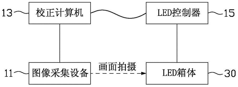
[0006] It can be seen from the above that for the existing calibration method of the LED cabinet in the factory, the LED cabinet needs to be manually placed in the preset position. If there is a deviation between the placement position and the set position, it will affect the data collection of the LED cabinet ;In addition, images of multiple cabinets cannot be collected at the same time; in addition, two calibration personnel are required to move the cabinets and one calibration personnel is required. The cooperation between the three people leads to longer time-consuming manual calibration

Method used


Image

  • Luminance and chrominance correction production line for LED (light-emitting diode) display modules
  • Luminance and chrominance correction production line for LED (light-emitting diode) display modules
  • Luminance and chrominance correction production line for LED (light-emitting diode) display modules

Examples


Embodiment Construction

[0025] In order to make the above objects, features and advantages of the present invention more comprehensible, specific implementations of the present invention will be described in detail below in conjunction with the accompanying drawings.

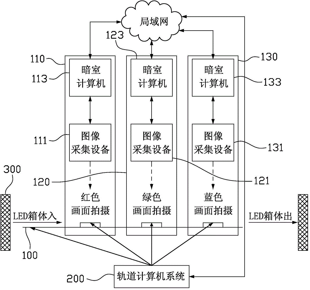
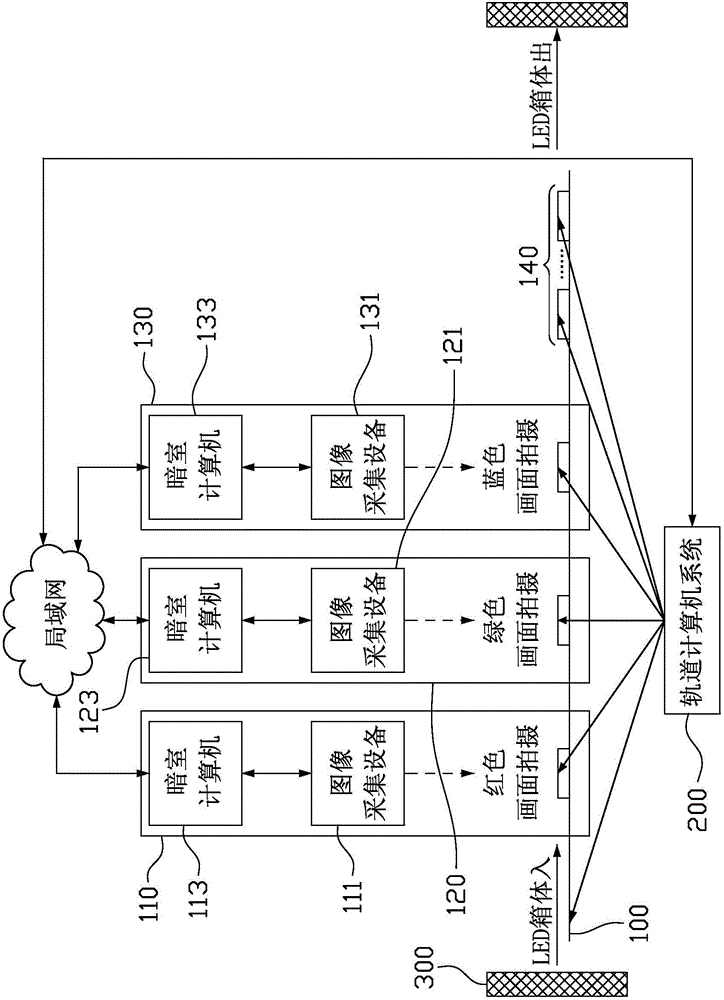
[0026] See figure 2 , which is a schematic diagram of the system architecture of a production line for brightness and chromaticity correction of LED display modules according to an embodiment of the present invention. Such as figure 2 The LED display module brightness and chromaticity correction production line includes: a track 100, a plurality of darkroom stations 110, 120, 130 arranged on the track 100, image acquisition equipment 111, 121, 131, darkroom computers 113, 123, 133 and a track computer system 200.

[0027] The image acquisition devices 111, 121, 131 are respectively arranged in the darkroom workstations 110, 120, 130, and the darkroom computers 113, 123, 133 are signally connected to the image acquisition devices 111...


PUM


Abstract

The invention relates to a luminance and chrominance correction production line for LED (light-emitting diode) display modules. The production line comprises a track, a plurality of stations, a plurality of image acquisition devices and a track computer system, wherein the stations are arranged on the track and include a plurality of first darkroom stations; the image acquisition devices are arranged in the first darkroom stations respectively, and used for performing image shooting on pictures different in color and sequentially displayed by the to-be-corrected LED display modules loaded on the track respectively to obtain color image data; the track computer system is used for controlling the motion of the track and controlling the to-be-corrected LED display modules to display the pictures different in color, and is in signal connection with the image acquisition devices to obtain the color image data. According to the production line, various color image information of the LED display modules is acquired in an assembly-line manner through the image acquisition equipment, so that the correction efficiency is improved, the data acquisition is relatively accurate, the data acquisition errors caused by correction of different LED display modules by different image acquisition devices are avoided, and the correction manpower is reduced.

Description

technical field [0001] The invention relates to the technical field of display correction, in particular to a production line for brightness and chromaticity correction of LED display modules. Background technique [0002] With the development of the LED display industry, the application fields of LED display are becoming more and more extensive. Advertising media, road traffic information display, dispatching command center information display, performances and gatherings are widely used in LED display. However, these displays will more or less have uneven phenomena such as mosaics caused by brightness and chromaticity deviations. It is necessary to use image acquisition equipment to correct each LED light to make the LED display screen smooth as a mirror. [0003] The calibration of the LED cabinet only needs to be carried out in the factory building, which consumes relatively little manpower and material resources. At present, display manufacturers tend to choose the box...

Claims


Application Information

Patent Timeline
IPC IPC(8): G09G3/32
CPCG09G3/006G09G2320/0233G09G2320/0242G09G2320/0295G09G2320/0626G09G2320/0666G09G2320/0693
Inventor 赵星梅
Owner XIAN NOVASTAR TECH
Learn More