Dry-type transformer

A dry-type transformer and transformer technology, applied in the field of transformers, can solve the problems of chaotic cable routing, high cost, and long connecting wires, and achieve the effects of standard cable routing, easy installation and maintenance, and cost reduction

Inactive Publication Date: 2015-04-29
WUHU JINNIU ELECTRIC
View PDF6 Cites 2 Cited by
  • Summary
  • Abstract
  • Description
  • Claims
  • Application Information

AI Technical Summary

Problems solved by technology

This kind of dry-type transformer has disadvantages, such as: the connection line connecting the high-voltage access terminal and the coil terminal is long, and the cost is high; and the various cables of the transformer are chaotic.

Method used


Image

  • Dry-type transformer
  • Dry-type transformer

Examples


Embodiment

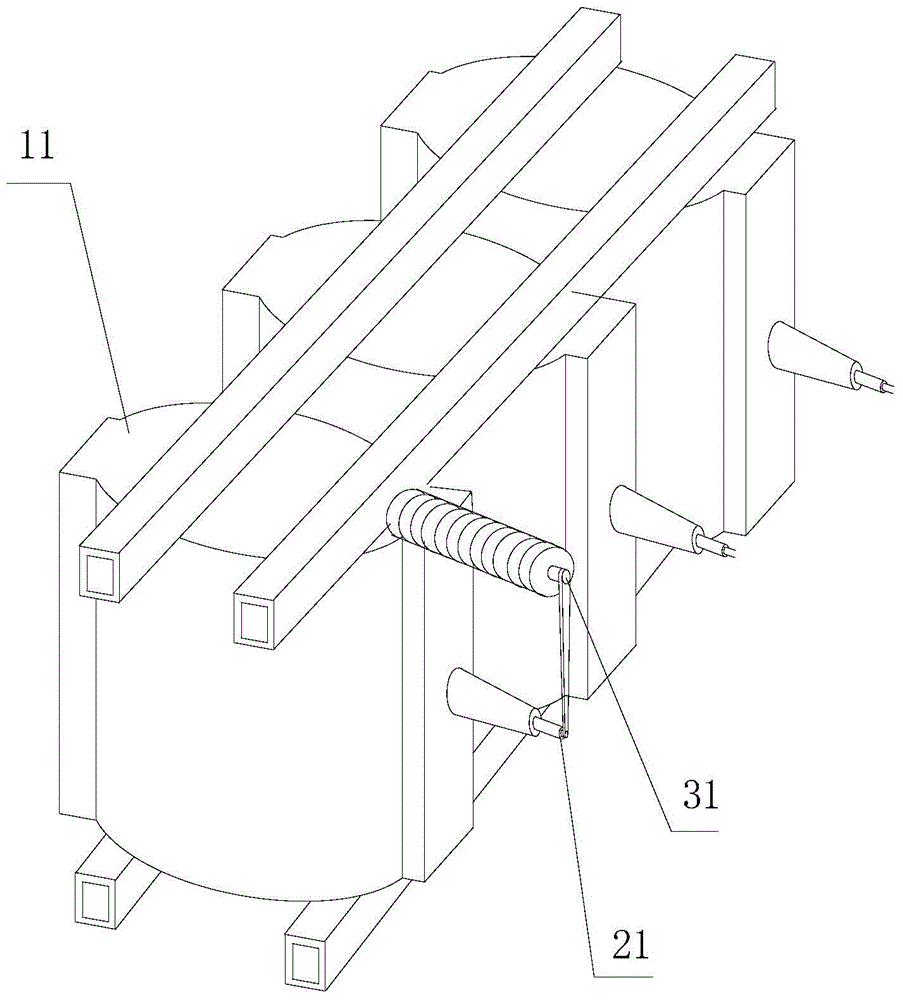
[0022] figure 1 The basic structural diagram of the dry-type transformer of the embodiment of the present invention is schematically given, as figure 1 As shown, the dry-type transformer includes:

[0023] A cabinet, a transformer body and a base, the transformer body adopts a dry-type transformer 11, which is installed on the base in the cabinet; the transformer body has a high-voltage access terminal 31 and a coil terminal 21;

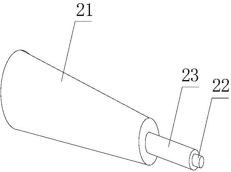
[0024] figure 2 Schematically provides the basic structural diagram of the coil terminal of the embodiment of the present invention, as figure 2 As shown, the insulating sleeve 23 is installed on the conductive post 22 inside the terminal post 21 .

[0025] The connection line between the end of the high-voltage access terminal and the terminal of the terminal is vertical, so that the distance between the high-voltage access terminal and the terminal is the shortest and the most economical.

[0026] "L"-shaped part, the "L"-shaped part is made ...


PUM


Abstract

The invention provides a dry-type transformer which comprises a cabinet body, a transformer body and a base, wherein the transformer body is arranged on the base in the cabinet body; the transformer body is provided with a high-voltage incoming end and a coil binding post; a connecting line between the end part of the high-voltage incoming end and the end part of the binding post is vertical. The dry-type transformer has the advantages of long service life, material-saving property and the like.

Description

technical field [0001] The invention relates to transformers, in particular to dry-type transformers. Background technique [0002] Power transformers are one of the main equipment in power plants and substations. The role of the transformer is multifaceted. It can not only increase the voltage to send electric energy to the power consumption area, but also reduce the voltage to the voltage used at all levels to meet the needs of power consumption. [0003] The existing dry-type transformer has a high-voltage access terminal and a coil terminal, and the ends of the two are not on the same vertical line. This kind of dry-type transformer has disadvantages, such as: the connection wire connecting the high-voltage access terminal and the coil terminal is relatively long, and the cost is relatively high; and the directions of various cables of the transformer are chaotic. Contents of the invention [0004] In order to solve the above-mentioned deficiencies in the prior art, ...

Claims


Application Information

Patent Timeline
Patent Type & Authority Applications(China)
IPC IPC(8): H01F27/28H01F27/32H01F27/30
Inventor 刘朝振陈明珠崔伟林
Owner WUHU JINNIU ELECTRIC
Why Eureka
Try Eureka