Mixing torque motor and traction machine adopting same

A technology of torque motors and motors, applied in the field of motors, can solve the problems of increased overall cost, difficulty in processing and installation, and low work efficiency, and achieve the effects of reducing the cost of the whole machine, saving the amount of magnetic steel, and reducing the cost of the motor

Inactive Publication Date: 2015-04-29
浙江西子富沃德电机有限公司
View PDF5 Cites 4 Cited by
  • Summary
  • Abstract
  • Description
  • Claims
  • Application Information

AI Technical Summary

Problems solved by technology

The three-phase asynchronous motor has large volume, high noise, low working efficiency, and is equipped with a deceleration device with a complex structure, which makes the structure of the entire traction machine complex and the overall cost increases
The motor does not use permanent magnets, and the cost is low, but the torque ripple is large, and the running noise and vibration are relatively large
[0004] Another hybrid torque motor is disclosed in the prior art, which can utilize permanent magnet torque and reluctance torque at the same time. For example, the patent document with the patent application number CN201210472407.5 discloses a permanent magnet reluctance type in-wheel motor , the disclosed rotor structure is equipped with magnets of the same polarity, with arc-shaped salient poles and magnetically conductive convex bodies at intervals, claiming that the amount of magnets can be reduced, but this structure only uses magnets of one polarity. The potential distortion is large, the torque ripple is large, and the position sensor is not

Method used


Image

  • Mixing torque motor and traction machine adopting same
  • Mixing torque motor and traction machine adopting same
  • Mixing torque motor and traction machine adopting same

Examples


Embodiment Construction

[0036] In order to make the purpose, technical solution and beneficial technical effect of the present invention clearer, the content and specific implementation methods of the present invention will be further described in detail below in conjunction with the accompanying drawings.

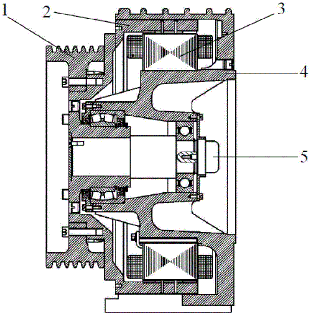
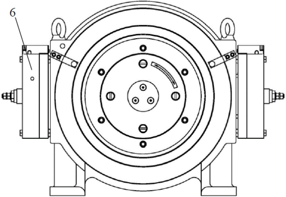
[0037] Such as figure 1 with figure 2 As shown, the hybrid torque elevator traction machine includes a relatively rotatable rotor 2 and a stator 3. There are multiple tooth poles on the stator core, which are made of laminated silicon steel sheets. Located on the periphery of the stator 3, the stator 3 and the rotor 2 can rotate relative to each other, the traction wheel 1 is connected to the rotor 2, the rotor 2 and the stator 3 are installed on the frame 4, and the frame 4 is integrated with the overall base of the traction machine. The overall structure is simple and convenient. The sensor 5 is installed in the base 4, the controller detects the position of the rotor 2 according to the sen...


PUM


Abstract

The invention discloses a mixing torque motor which includes stators and rotors positioned on the peripheries of the stators, wherein the rotors include barrel-shaped rotor iron cores; a plurality of permanent magnets are distributed on the inner walls of the rotor iron cores at intervals; the polarities of two adjacent permanent magnets are opposite, and permeability magnetic materials are arranged between the two adjacent permanent magnets. The invention further discloses a traction machine adopting the mixing torque motor. Compared with a conventional gearless permanent magnet synchronous traction machine, the traction machine provided by the invention reduces magnetic steel using amount and lowers the motor cost, so that the complete machine cost of the traction machine is reduced and the structure is compact and the size is small; operational maximum speed of the traction machine is further improved through flux weakening speed expansion due to structural salient poles added on the rotors; the degree of difficulty of detecting positions of rotor magnetic poles through adopting the position sensor free control algorithm is reduced and greater possibility of de-encoding of the permanent magnet traction machine is provided due to the existence of the structural salient poles.

Description

technical field [0001] The invention belongs to the technical field of motors, and in particular relates to a hybrid torque motor and the traction machine using the hybrid torque motor. Background technique [0002] At present, elevator traction machines are mainly three-phase asynchronous motors or permanent magnet synchronous motors. The three-phase asynchronous motor has large volume, high noise, low working efficiency, and is equipped with a deceleration device with a complex structure, which makes the structure of the entire traction machine complex and the overall cost increases. The permanent magnet synchronous traction machine does not need a deceleration device, and has high efficiency and low noise. It gradually replaces the three-phase asynchronous motor, but the rare earth material is expensive, which limits the development of the permanent magnet synchronous motor. [0003] In the prior art, a switched reluctance motor has been developed, which uses the princip...

Claims


Application Information

Patent Timeline
IPC IPC(8): H02K21/22H02K1/27B66B11/04
Inventor 范坚坚马勇明李庆潘钟骏祥王立强
Owner 浙江西子富沃德电机有限公司
Why Eureka
Try Eureka