
Flow-induced vibration power generation device based on deformable support

A technology of vibration power generation and flow induction, applied in the direction of electromechanical devices, electrical components, etc., can solve the problem of limiting the economy and practicability of VIVACE ocean current energy utilization devices, reducing the energy conversion coefficient of VIVACE ocean current energy utilization devices, and increasing the frictional resistance of transmission parts and other problems, to achieve the effect of convenient manufacture and construction, reliable performance, and reduced fluid resistance

Inactive Publication Date: 2015-04-29
TIANJIN UNIV
View PDF5 Cites 5 Cited by
  • Summary
  • Abstract
  • Description
  • Claims
  • Application Information

AI Technical Summary

Problems solved by technology

However, the shortcomings of the VIVACE ocean current energy utilization device are also very prominent
1) There are too many mechanical transmission parts, because marine biological debris is attached to the mechanical transmission parts, resulting in increased frictional resistance of the transmission parts, which reduces the energy conversion coefficient of the VIVACE sea current energy utilization device; 2) It is difficult to prevent underwater corrosion, because With mechanical transmission, simple anti-corrosion coating protection cannot be used at the sliding / rotating connection nodes of components; 3) Additional support structure, VIVACE ocean current energy utilization device module requires two additional columns to support the columns suspended on it, so The cost is high, and the column has a hindering effect on the ocean current, which reduces the energy conversion coefficient of the VIVACE ocean current energy utilization device
These defects limit the economy and practicability of the VIVACE ocean current energy utilization device

Method used


Image

  • Flow-induced vibration power generation device based on deformable support
  • Flow-induced vibration power generation device based on deformable support
  • Flow-induced vibration power generation device based on deformable support

Examples


Embodiment Construction

[0023] The present invention will be further described below in conjunction with the accompanying drawings.

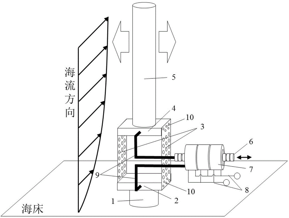
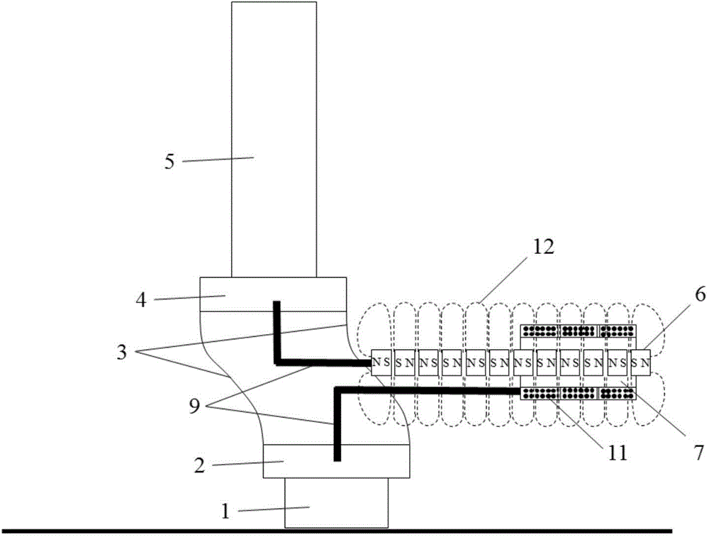
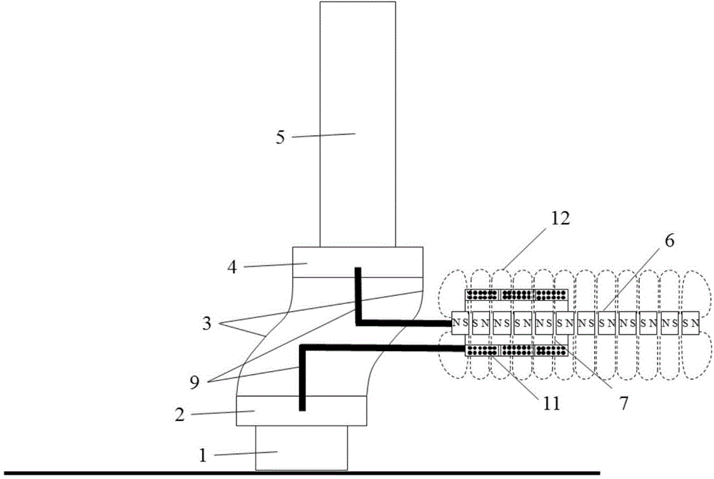
[0024] like Figure 1 to Figure 4 Shown: a fluid-induced vibration power generation device based on a deformable support, including a cylinder 5 and a generator system, the cylinder 5 is a hollow and airtight cylinder inside, and the lower end of the cylinder 5 is embedded and connected to the upper platform 4, and the upper platform 4. The elastic connecting plate 3 is connected with the lower platform 2, which is made of steel plate with through holes, and the elastic connecting plate 3 is fixedly connected to the upper platform 4 and the lower platform through staggered bolts On both sides of the platform 2, the elastic connecting plate 3 can only undergo S-shaped bending deformation to form a deformable support. The lower platform 2 is embedded and connected with the support pile 1, and the lower end of the support pile 1 penetrates into the seabed to form the fou...


PUM


Abstract

The invention discloses a flow-induced vibration power generation device based on a deformable support. The device comprises a cylinder and a generator system, wherein an upper platform and a lower platform which are mutually connected through elastic connecting plates are arranged below the cylinder, the elastic connecting plates are correspondingly and fixedly connected onto two sides of the upper platform and the lower platform through staggered bolts, a support pile penetrating through a seabed is fixedly connected with the lower platform, the generator system comprises a permanent-magnet linear generator and a linear magnetic rod inserted in a coil of the permanent-magnet linear generator, and the linear magnetic rod and the permanent-magnet linear generator are connected with side surfaces of the upper platform and the lower platform respectively through connecting rods. The device has the advantages that the device is simple in structure, high in reliability, free of sliding / rotating nodes, low in cost, high in efficiency, long in service life and the like, and the economy and the engineering applicability of the flow-induced vibration power generation device are enhanced.

Description

technical field [0001] The invention relates to the field of new energy power generation equipment and fluid mechanics, and more particularly, to a flow-induced vibration power generation device based on a deformable support. Background technique [0002] Nowadays, with the rapid development of the global economy, fossil fuel resources are increasingly depleted, and the environmental pollution caused by them is becoming more and more serious. The development and utilization of clean and renewable energy has become a strategic choice for countries in the world today. Among the many clean energy sources, ocean current energy has attracted more and more attention from the scientific and engineering circles for its efficient development and utilization due to its advantages of large scale, stable flow, and wide distribution. According to statistics, the global available ocean current energy is as high as 5 million megawatts. China's ocean currents are also very rich, with the T...

Claims


Application Information

Patent Timeline
IPC IPC(8): H02K35/02
Inventor 及春宁许栋张金凤
Owner TIANJIN UNIV
Learn More