
A passive light-splitting rs-485 optical fiber bus embedded terminal
A RS-485, embedded terminal technology, applied in the field of industrial manufacturing, can solve the problem of not guaranteeing high-speed long-distance communication requirements, communication rate drop, etc., to achieve the effects of wide dynamic range, reduced pulse width distortion, and simple system
- Summary
- Abstract
- Description
- Claims
- Application Information
AI Technical Summary
Problems solved by technology
Method used
Image

Examples
Embodiment
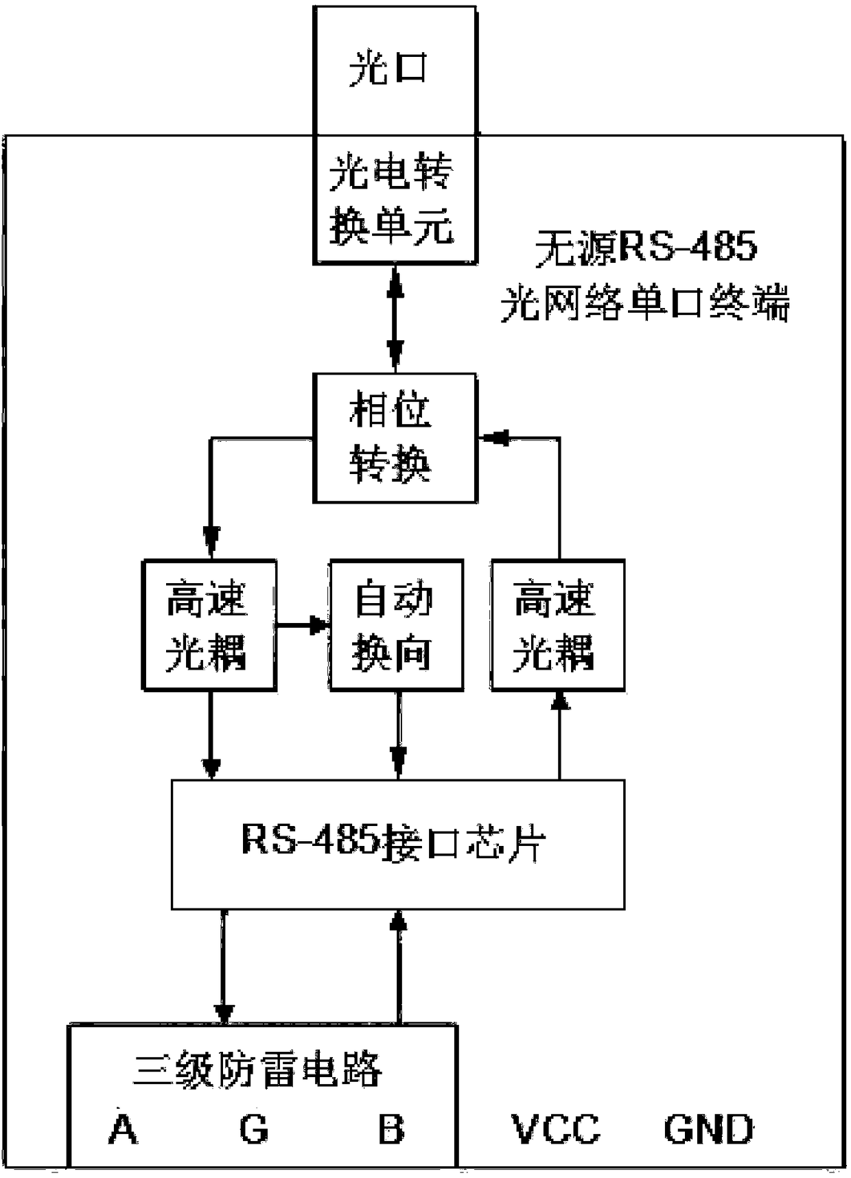
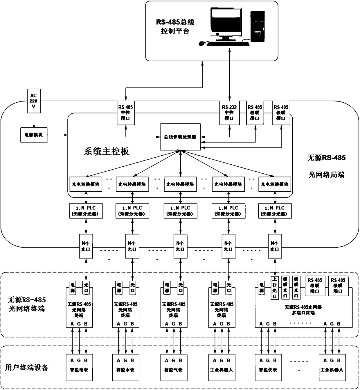
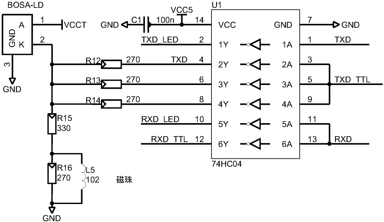
[0035] Example: see Figure 1 to Figure 8 This embodiment provides a passive RS-485 optical fiber bus embedded terminal, the two ends of which are respectively connected to the passive RS-485 optical network central office and terminal equipment of the passive optical RS-485 optical bus, which include a power module , Photoelectric conversion unit, RS-485 driver chip, high-speed optocoupler isolation circuit, non-polarity automatic transceiver commutation circuit and three-level lightning protection circuit, among which the photoelectric conversion unit is connected to one end of the high-speed optocoupler isolation circuit, and the high-speed optocoupler isolation circuit is another One end is connected to the non-polarity automatic transceiver commutation circuit and the RS-485 driver chip, and the RS-485 driver chip is connected to the three-level lightning protection circuit; the photoelectric conversion unit includes a transmitting unit and a receiving unit; the transmittin...
PUM
 Abstract
Description
Claims
Application Information