Supercharge Your Innovation With Domain-Expert AI Agents!

Controlled directional solidification of silicon

A technology of directional solidification and crucibles, applied in self-solidification, polycrystalline material growth, crystal growth, etc., can solve the problems of expensive and difficult to maintain cooling or heating conduits

Active Publication Date: 2015-04-29
SILICOR MATERIALS INC
View PDF5 Cites 2 Cited by
  • Summary
  • Abstract
  • Description
  • Claims
  • Application Information

AI Technical Summary

Problems solved by technology

Such temperature control mechanisms can involve relatively expensive and difficult to maintain cooling or heating conduits within the directional solidification crucible

Method used


Image

  • Controlled directional solidification of silicon
  • Controlled directional solidification of silicon
  • Controlled directional solidification of silicon

Examples


Embodiment approach 1

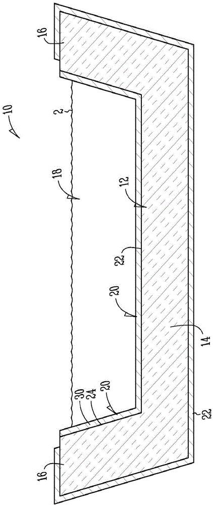
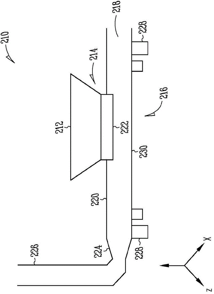
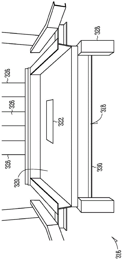
[0146] Embodiment 1 provides an apparatus for directional solidification comprising: a directional solidification crucible comprising a bottom; and a cooling platform comprising: a first surface defining an aperture configured to receive the directional solidification a portion of the bottom of the crucible, and a cooling conduit configured to provide a portion of the forced air to the portion of the bottom of the directional solidification crucible.

Embodiment approach 2

[0147] Embodiment 2. The apparatus of embodiment 1, wherein a plurality of sidewalls of the directionally solidified crucible comprise a hot face refractory material.

Embodiment approach 3

[0148] Embodiment 3. The apparatus of Embodiment 1 or 2, wherein the bottom of the directional solidification crucible comprises a conductive refractory material.


PUM


Abstract

The present invention relates to an apparatus and method for directional solidification of silicon. The apparatus can use a cooling platform to cool a portion of a bottom of a directional solidification crucible. The apparatus and method of the present invention can be used to make silicon crystals for use in solar cells.

Description

[0001] related application [0002] This application claims priority to US Provisional Application No. 61 / 663,940, filed June 25, 2012, which is hereby incorporated by reference in its entirety. Background technique [0003] Solar cells are a viable energy source by harnessing their ability to convert sunlight into electricity. Silicon is a semiconductor material used in the manufacture of solar cells; however, limitations on the use of silicon relate to the cost of purifying it to solar grade (SG). [0004] Several techniques are known for preparing silicon crystals for solar cells. Most of these techniques operate on the principle that when silicon solidifies from a molten solution, undesired impurities tend to remain in the molten solution. For example, float zone technology can be used to create monocrystalline ingots and use moving liquid regions within a solid material to move impurities to the edge of the material. In another example, the Czochralski technique can b...

Claims


Application Information

Patent Timeline
IPC IPC(8): C30B11/00C30B28/06C30B29/06C30B35/00B22D27/04
CPCB22D27/045C30B11/002C30B11/003C30B29/06Y10T117/1092
Inventor 阿布达拉·奴里
Owner SILICOR MATERIALS INC
Features
  • R&D
  • Intellectual Property
  • Life Sciences
  • Materials
  • Tech Scout
  • Unparalleled Data Quality
  • Higher Quality Content
  • 60% Fewer Hallucinations
Learn More