This helps you quickly interpret patents by identifying the three key elements:
Problems solved by technology
Method used
Benefits of technology
Problems solved by technology
However, the tray must be in a shape that can be installed in the device. Use a dedicated tray. Since the tray is dedicated, the number of test tubes that can be loaded on one tray has already been determined. When subdivided storage is required and the tray can be loaded If the number of samples above the upper limit of the sample is stored, it cannot be handled
Method used
Image
Click on the blue label to locate the original text in one second.
Reading with bidirectional positioning of images and text.
Examples
Embodiment 1
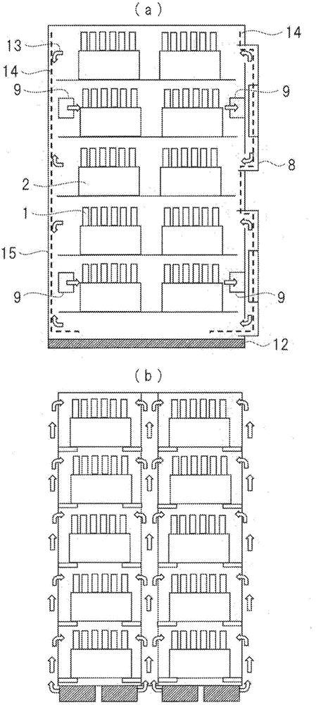
[0077] The structure of the sample storage unit 7 is as follows: image 3 (a) shown.
[0078] image 3 In the sample storage section, the sample storage section has five layers of shelves, and two sample trays can be accommodated on one shelf.
[0079] In the sample storage section 7 , the cooling air cooled by the cooling unit 8 is circulated by the blower fan 9 , whereby the temperature in the sample storage section 7 is kept uniformly cold. The flow of cooling air in the sample storage unit 7 is as follows: image 3 Arrow 13 in (a). As a result, even if the sample is stored in any position in the sample storage section configured in multiple layers, it can be uniformly kept cold and stored.
[0080] In addition, since the inside of the sample storage unit is kept cold, the inside of the sample tray may be dewed due to the opening and closing of the shutter mechanism or the like. If dew accumulates in the sample storage portion, not only bacteria may multiply, but also ...
Embodiment 2
[0101] The structure of the sample storage unit 7 is as follows: image 3 (b) shown.
[0102] image 3 In the sample storage section, the sample storage section has five layers of shelves, and two sample trays can be accommodated on one shelf.
[0103] A cooling unit is disposed on the lower surface of the specimen storage unit 7 , and the cooling surface of the cooling unit is configured to be in close contact with the bottom surface of the specimen storage unit. Simultaneously with the operation of the sample storage device, the cooling unit operates to cool the bottom surface of the sample storage unit. By using a material with good heat conductivity such as aluminum or copper for the bottom surface and the wall surface of the specimen storage unit, cool air is conducted from the bottom surface to the wall surface, thereby cooling the entire wall surface of the storage unit. The interior of the storage room is kept cold by the heat protection of the cooled wall surface. ...
Embodiment 3
[0119] The box is constructed as Figure 9 as well as Figure 10 shown.
[0120] The specimen tray can be expanded by using the cassette.
[0121] Such as Figure 9 as well as Figure 10 In that way, there are six protrusions 81 on the upper surface in the case 80 . With respect to the cassette 80 , there are six recesses 91 a on the bottom surface of the tray 90 a at positions facing the protrusions 81 , and the operator fits into the recesses 91 a of the tray 90 a in cooperation with the protrusions 81 of the cassette 80 . By using the recess, the position of the tray 90a to be erected can be erected without deviation every time. In addition, if the orientation of the tray 90a is in the wrong direction at this time, the positions of the protrusions 81 and the recesses 91a will not match, and the tray 90a cannot be erected.
[0122] In addition, here, for example, when the tray 90b capable of carrying 50 specimens is intended to be erected, the three recesses 91b on the...
PUM
Abstract
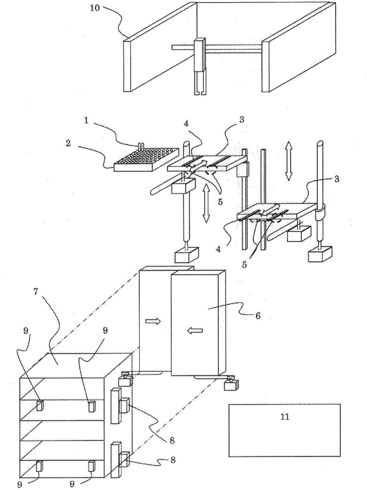
In conventional sample housing devices, when there has been a re-testing request for a housed sample, it has been necessary for an operator to search for the relevant sample from among the housed samples and reintroduce same to a device for re-testing, and so time and effort was needed. This sample housing device is provided with: a sample conveyance line for conveying a sample installed at a holder for conveying samples for which pre-processing has been completed; a lift mechanism that can, in the front / back and up / down directions, drive a sample tray at which a sample is installed; a sample chuck mechanism that moves samples from the sample acquisition position of the sample conveyance line to a sample tray on the lift mechanism; a sample housing section provided with a sample housing space that receives sample trays from the lift mechanism and that is tiered in the up / down direction, and housing a plurality of sample trays in a manner so as to be able to be cold stored in the left-right direction; a shutter mechanism that can open / close when transferring sample trays between the lift mechanism and the sample housing section; and a control unit that controls each of the mechanisms.
Description
technical field [0001] The present invention relates to a sample storage device for storing parent test tubes and preserved child samples after pretreatment and analysis processing, and a system including the sample storage device. Background technique [0002] In the field of clinical examinations, specimens such as blood and urine collected from patients in hospitals are enclosed in test tubes, transported to the examination room or examination center of the hospital, and analyzed by an analysis device. A plurality of test tubes (hereinafter referred to as parent sample tubes) used when centrifuging a test tube containing a sample (hereinafter referred to as parent sample tube) when loading into the analyzer, unsealing the parent sample tube, and dispensing the sample from the parent sample tube (hereinafter referred to as (referred to as sub-specimen tubes) preparation, sub-tube dispensing, and other pretreatments, and then transported to the analyzer for analysis. The s...
Claims
Application Information
Patent Timeline
Application Date:The date an application was filed.
Publication Date:The date a patent or application was officially published.
First Publication Date:The earliest publication date of a patent with the same application number.
Issue Date:Publication date of the patent grant document.
PCT Entry Date:The Entry date of PCT National Phase.
Estimated Expiry Date:The statutory expiry date of a patent right according to the Patent Law, and it is the longest term of protection that the patent right can achieve without the termination of the patent right due to other reasons(Term extension factor has been taken into account ).
Invalid Date:Actual expiry date is based on effective date or publication date of legal transaction data of invalid patent.

