Plant control apparatus

A technology for equipment control and equipment, which is applied in the control of combustion, adaptive control, electrical program control, etc., to achieve the effect of improving skills, improving reliability, and deepening understanding

Active Publication Date: 2012-07-04
HITACHI LTD
View PDF5 Cites 0 Cited by
  • Summary
  • Abstract
  • Description
  • Claims
  • Application Information

AI Technical Summary

Problems solved by technology

[0019] In addition, in the technology described in Patent Document 2, the state of the combustion furnace flame can be easily grasped, but for nitrogen oxides (NOx), carbon monoxide (CO) and the like Production of harmful components does not directly reveal causation

Method used


Image

  • Plant control apparatus
  • Plant control apparatus
  • Plant control apparatus

Examples


Embodiment 1

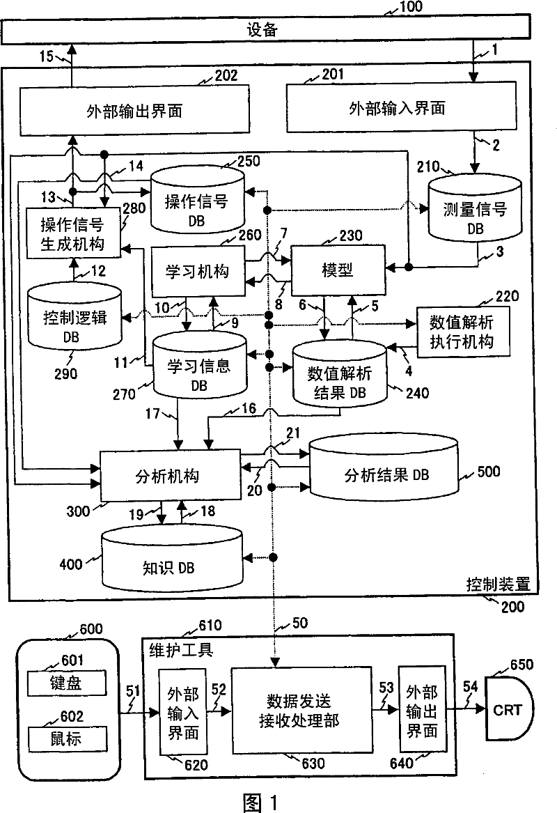
[0078] figure 1 is a block diagram showing the system configuration of Embodiment 1 of the device control device according to the present invention. figure 1 , the device 100 is controlled by the control device 200 .

[0079] In the control device 200 that controls a device to be controlled, a numerical analysis execution unit 220 , a model 230 , a learning unit 260 , an operation signal generation unit 280 , and an analysis unit 300 are provided as arithmetic units.

[0080] In addition, in the control device 200, a measurement signal database 210, a numerical analysis result database 240, an operation signal database 250, a learning information database 270, a control logic database 290, a knowledge database 400, and an analysis result database 500 are provided as databases.

[0081] In addition, an external input interface 201 and an external output interface 202 are provided in the control device 200 as interfaces with the outside.

[0082] In the control device 200 , ...

Embodiment 2

[0141] Next, Embodiment 2 in which the facility control device according to the present invention is applied to thermal power generation facilities will be described.

[0142] Furthermore, it goes without saying that the facility control device of the present invention can also be used when controlling facilities other than thermal power generation facilities.

[0143] Figure 13 It is a figure which shows the system structure of the thermal power generation facility 100.

[0144] The boiler 101 constituting thermal power generation equipment is provided with a burner 102 for supplying pulverized coal as a fuel obtained by finely pulverizing coal with a mill 110, primary air for transporting the pulverized coal, and secondary air for combustion adjustment, and uses The pulverized coal supplied through the burner 102 is burned inside the boiler 101 . Further, pulverized coal and primary air are introduced into the burner 102 through the pipe 142 , and the secondary air is int...


PUM


Abstract

The invention provides an equipment control device which analyzes the effect of altering operation signal in short time, obtains the physical reason of the effect and displays the analytical results. The equipment control device is provided with a measurement signal DB(210), an operation signal DB(250), a numerical value analysis executing unit DB(220), a numerical value analytical result DB(240), a model (230)used for estimating a value of a measurement signal for an operation signal; a learning unit (260) using the model, a learning information DB(270), a control logic DB(290) of information used by an operation signal generating unit (280), a knowledge DB(400) for equipment running characteristics, an analyzing unit (300) which processes the information in the numerical value analytical result DB(240) by information in the knowledge DB(400), learning information DB(270), operation signal DB (250) and measurement signal DB(210), wherein the analyzing unit comprises a learning base analyzing unit (310) checking adequacy of an operation method, a signal analyzing unit (320) for evaluating an effect of the operation signal upon the plant and presence / absence of an abnormal signal, and at least one of a knowledge DB updating unit (330) correcting information in the knowledge DB (400).

Description

technical field [0001] The present invention relates to equipment control devices for thermal power generation equipment and the like. Background technique [0002] In the equipment control device, the measurement signal from the equipment to be controlled is processed, and the operation signal to be given to the controlled object is calculated. An algorithm for calculating the operating signal is installed in the control device so that the measured signal of the device meets its target value. [0003] There is a PI (proportional-integral) control algorithm as an algorithm used for controlling the equipment. PI control is to multiply the deviation between the measurement signal of the device and its target value by the proportional gain, and then add it to the time-integrated value of the deviation, so as to derive the operation signal for the control object. A control algorithm using PI control can be visualized in a block diagram and it is clear how or why it works. Ty...

Claims


Application Information

Patent Timeline
Patent Type & Authority Patents(China)
IPC IPC(8): G05B13/02F23N5/18G05B19/42
Inventor 关合孝朗山田昭彦林喜治金田昌基江口彻清水悟深井雅之
Owner HITACHI LTD
Why Eureka
Try Eureka